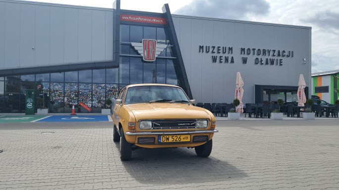
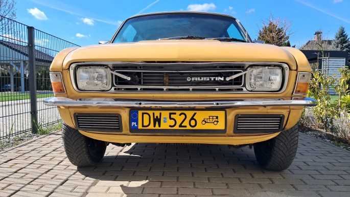
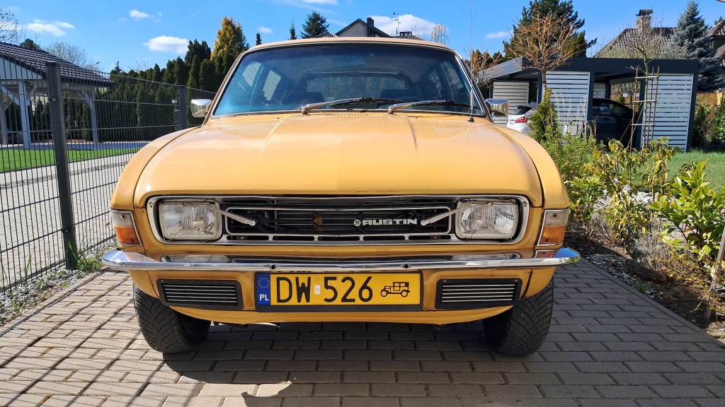
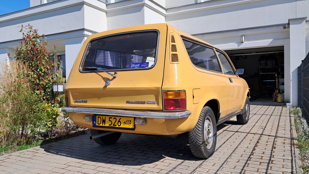
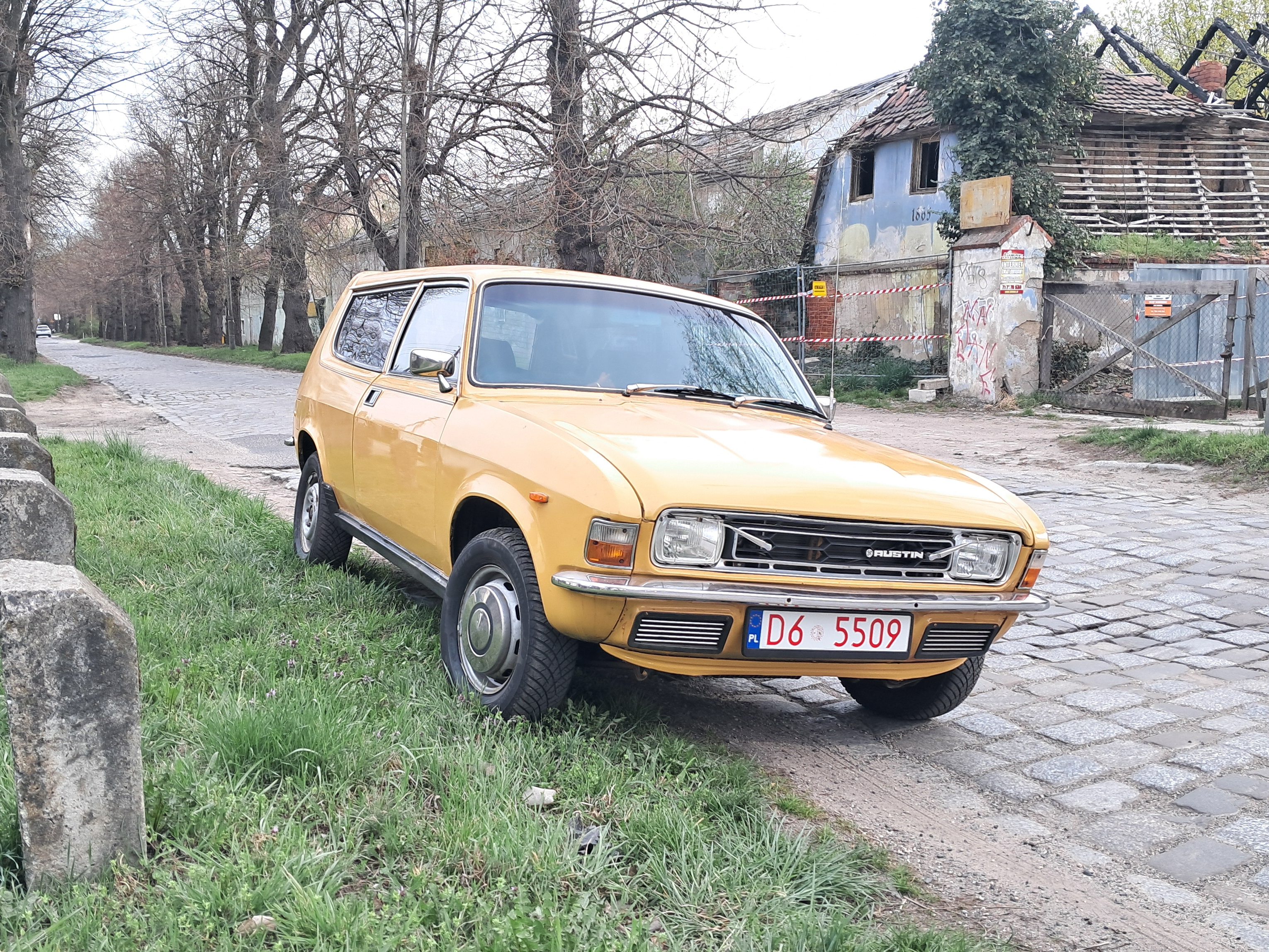
Projekt Agnetha Quarterly Report 2025 Q4

Executive summary

The final quarter of 2025 saw the planned engine rebuild pivot to invasive structural repairs before returning to course. While the “done-in-an-afternoon” welding tasks predictably expanded in scope, the engine rebuild has nonetheless proceeded ahead of schedule, bolstered by strategic outsourcing to professional machine shops. Agnetha is currently awaiting completion of the cylinder head renovations before final assembly and testing.

1. key performance indicators

Odometer12345 km
Distance travelled this quarter0 km
Furthest distance from home0 km
Breakdowns0

2. engineering work

2.1. welding YUCK

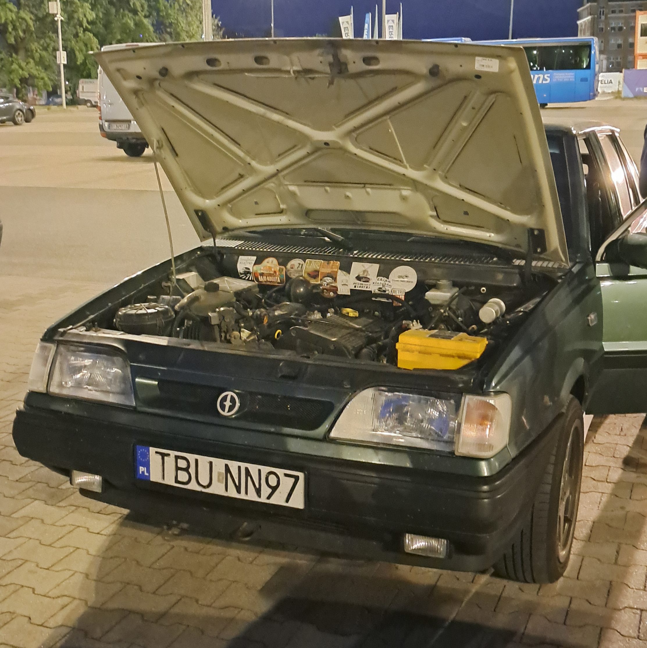
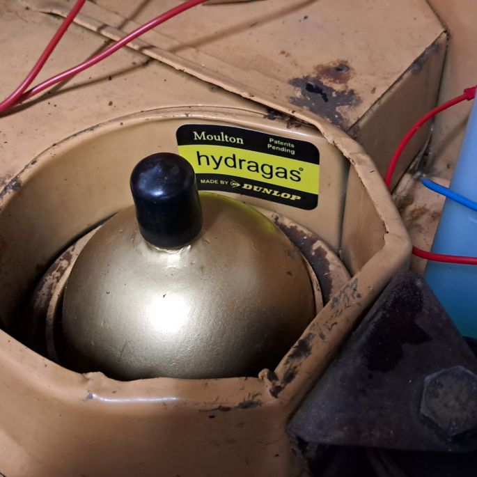
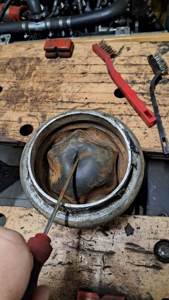
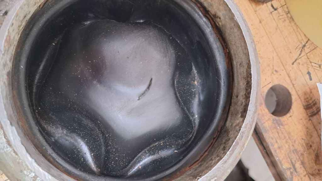
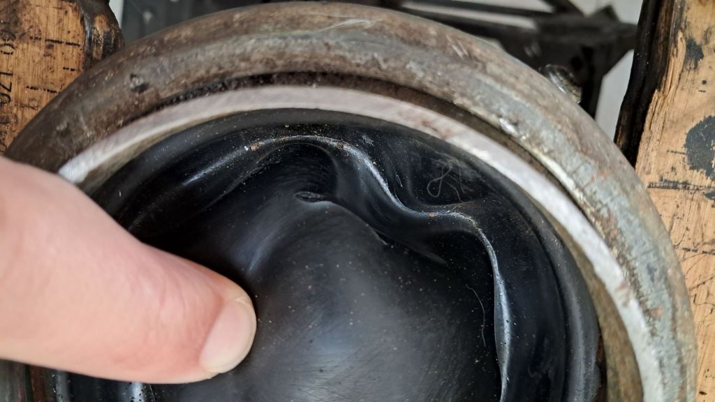
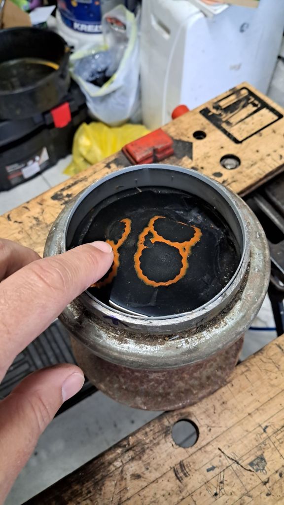
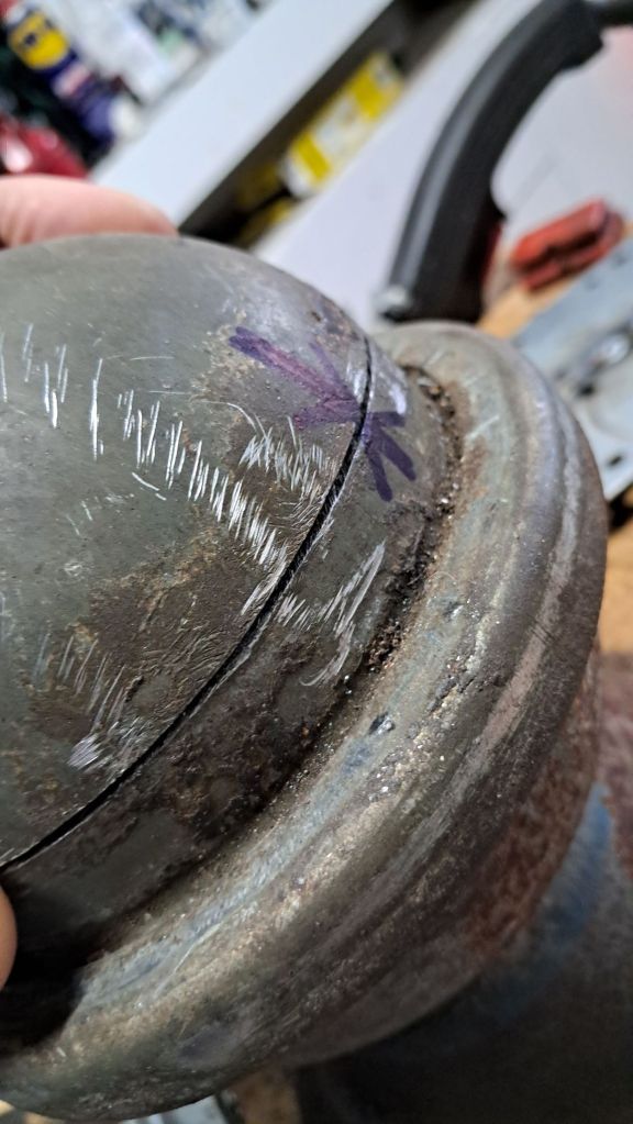
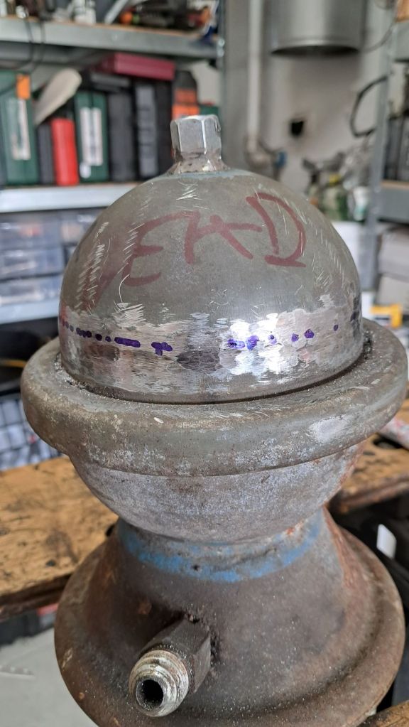
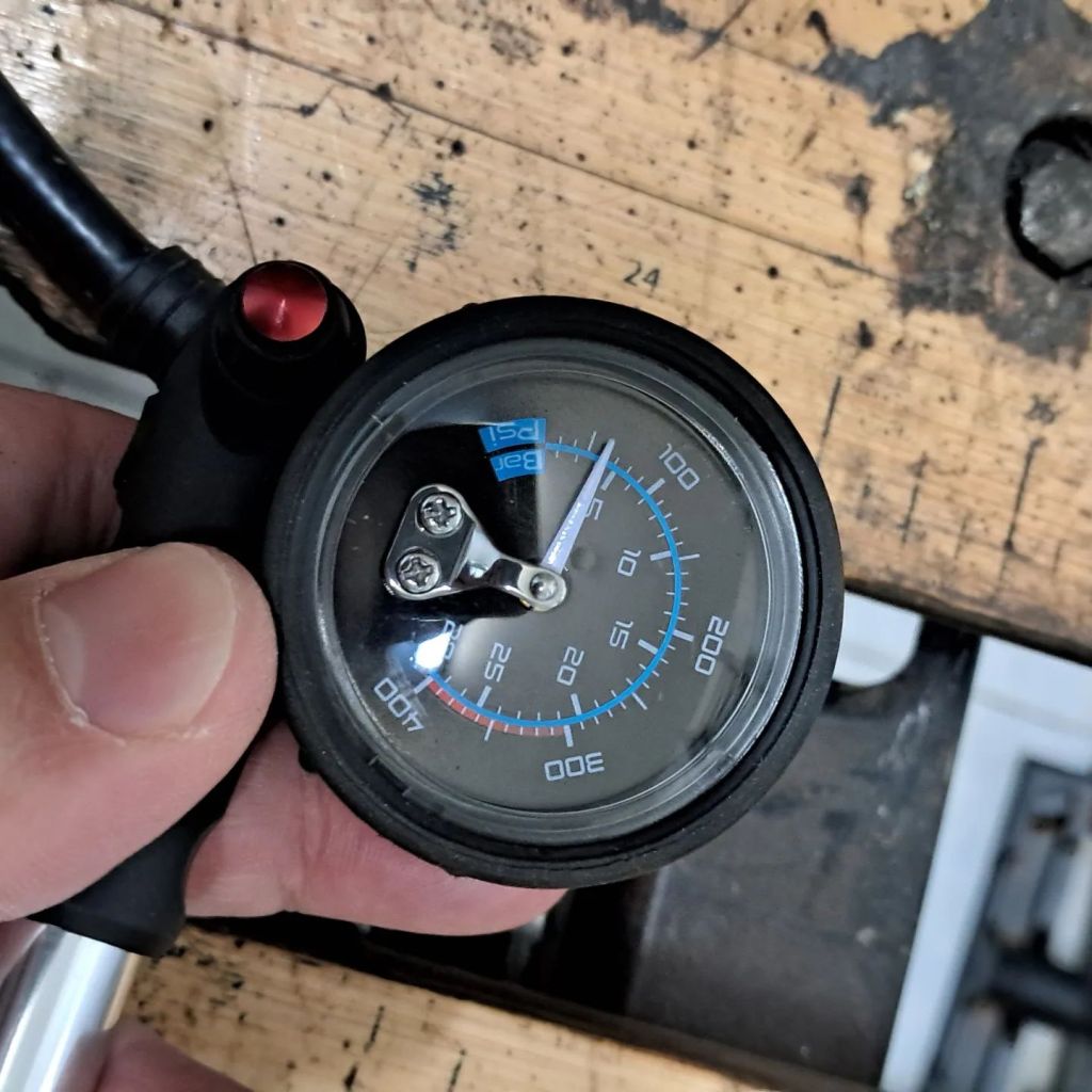
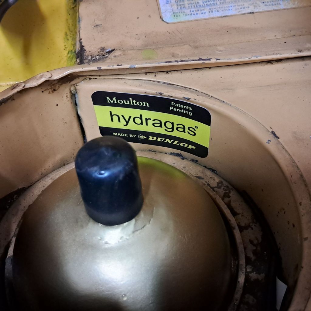
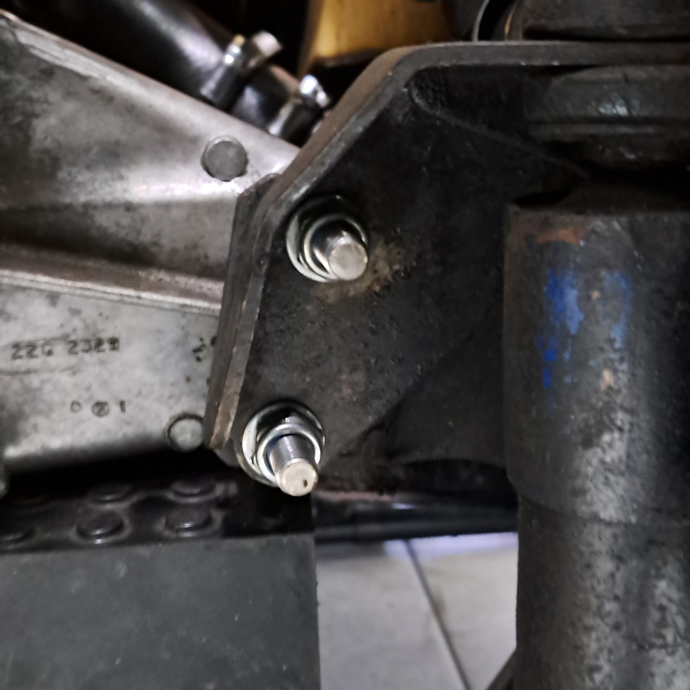
As is often the case, what started out as quick afternoon welding job soon turned into a painful ordeal lasting several weeks. I had noticed a small crack appearing near on the passenger side suspension tower around where the lower swing arm is mounted, and a hole above where the Hydragas sphere emerges from the tower. Half expecting both of them to be much worse than they seemed I was relieved to find the rust was only on the surface and neither the crack nor the hole extended very far when I wire-wheeled around them.

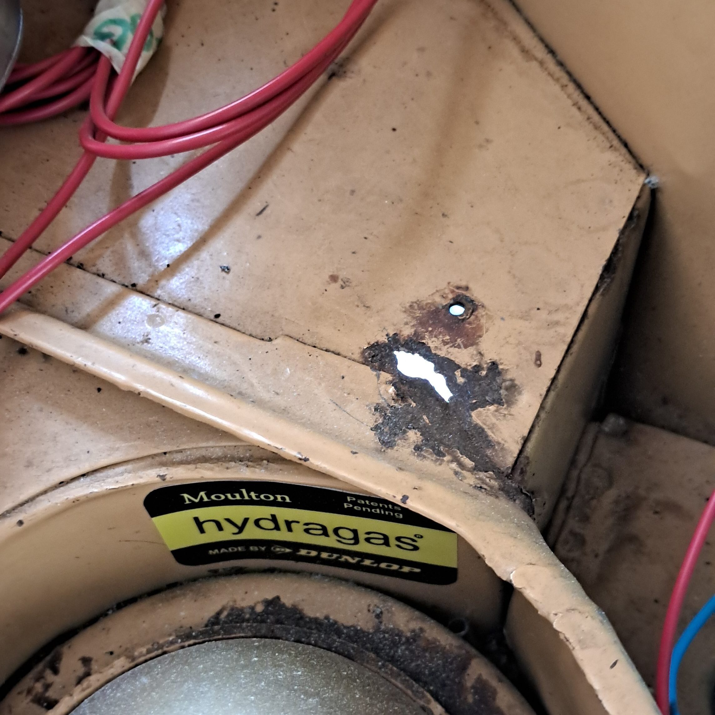
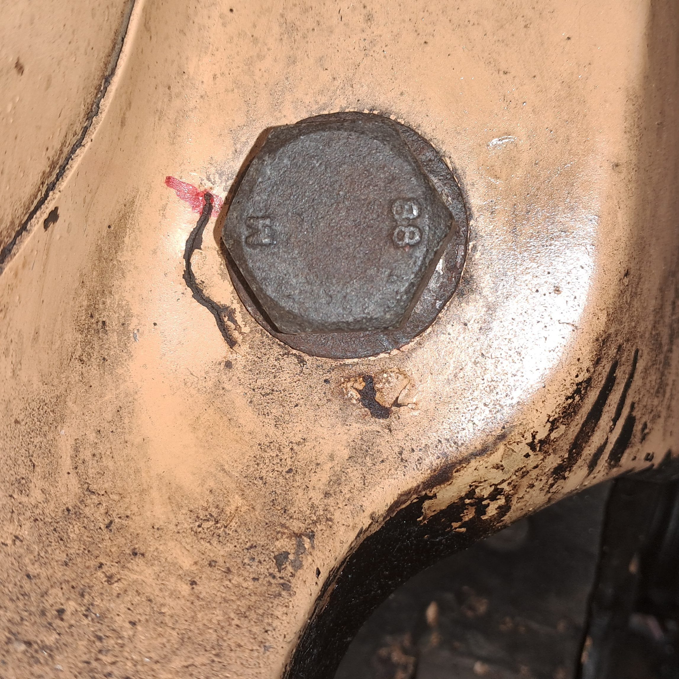
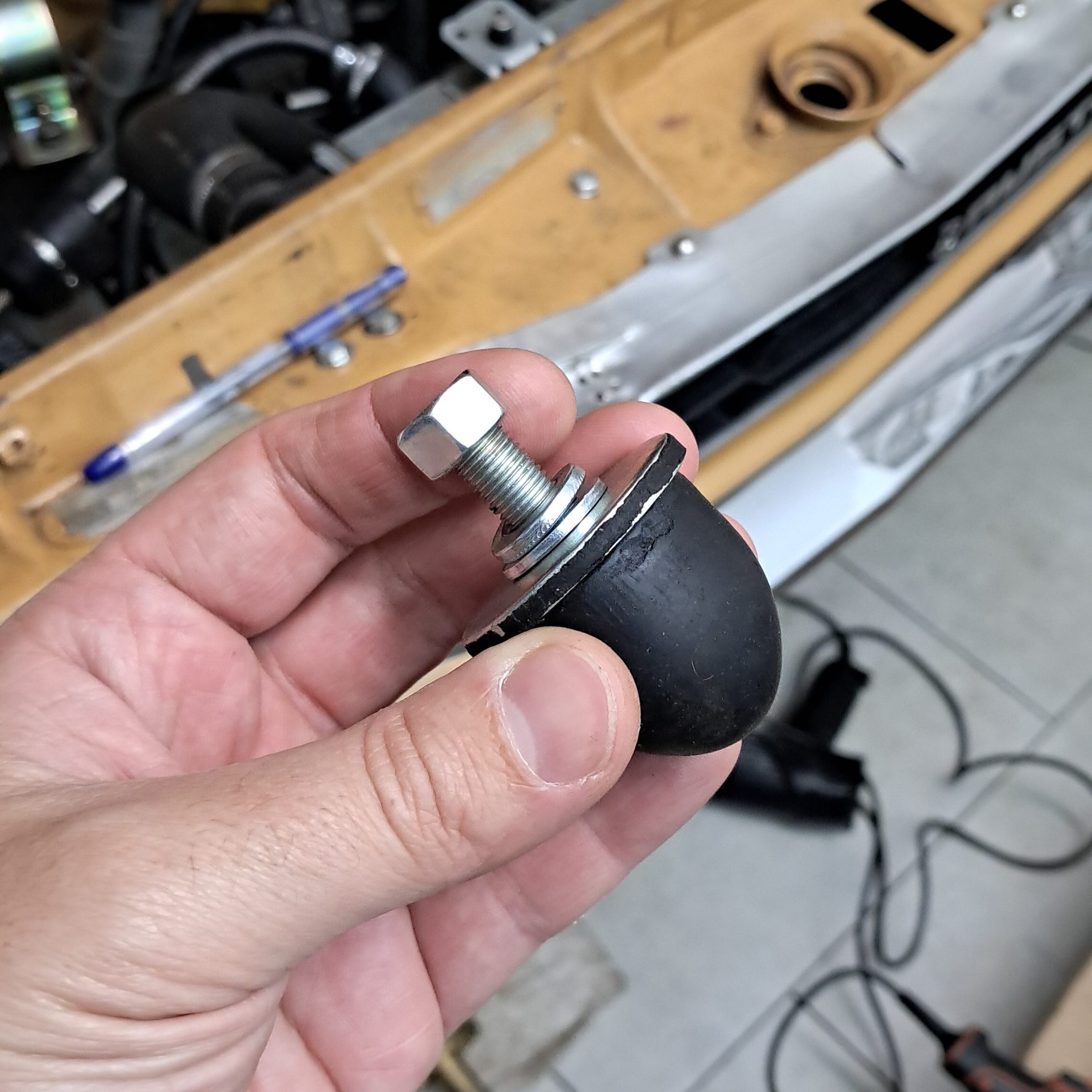
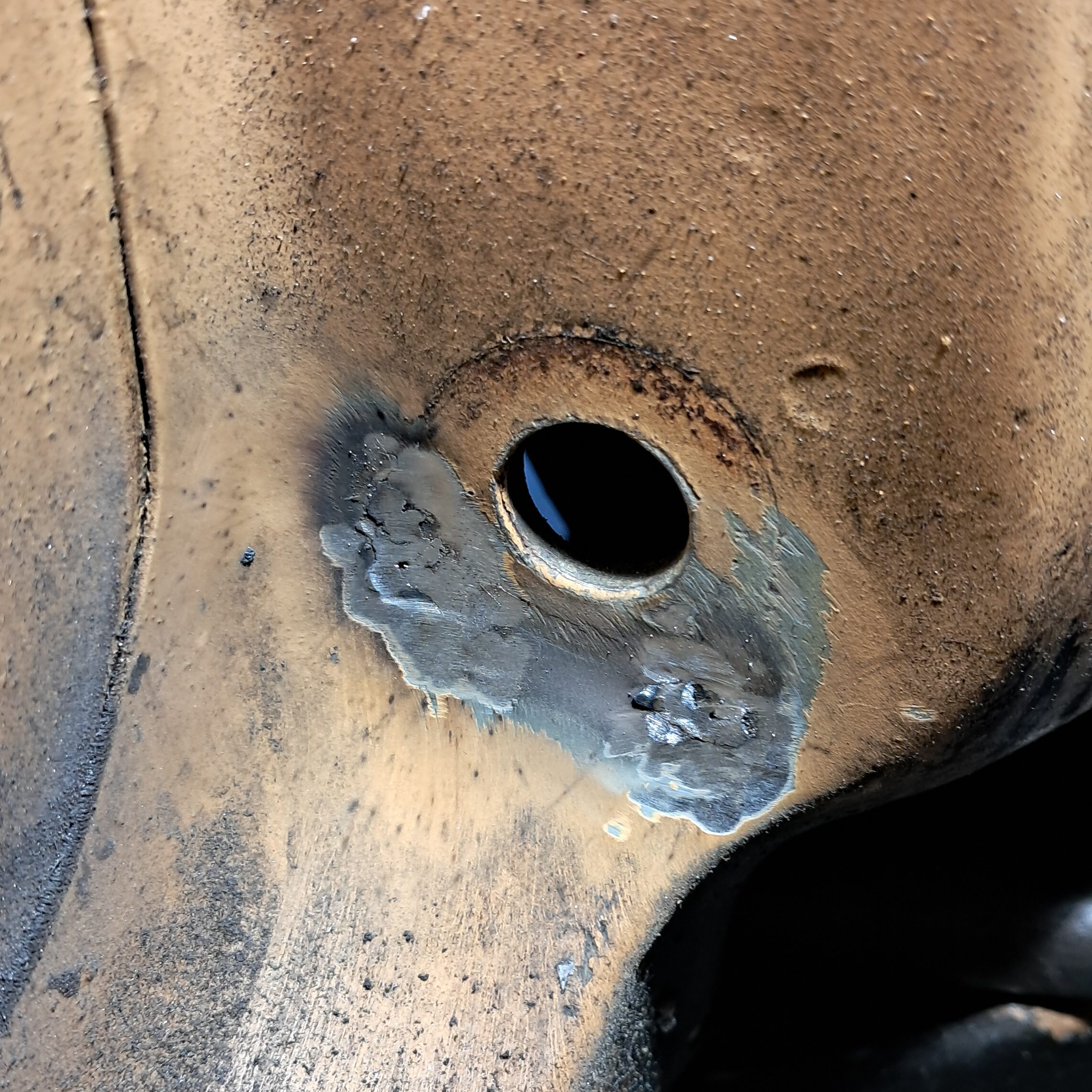
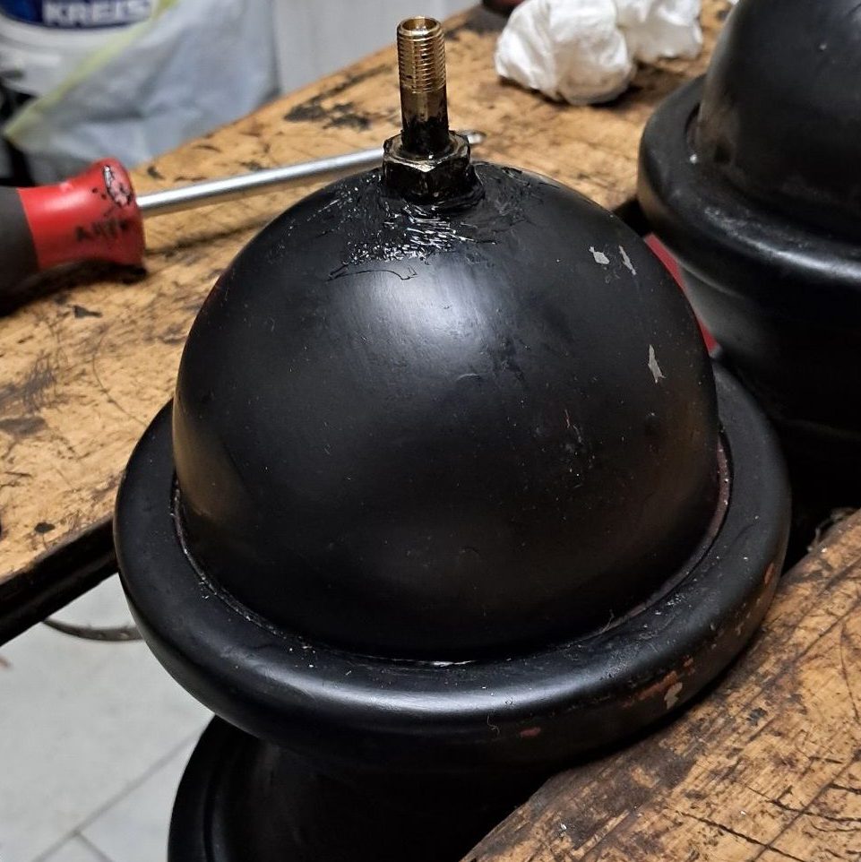
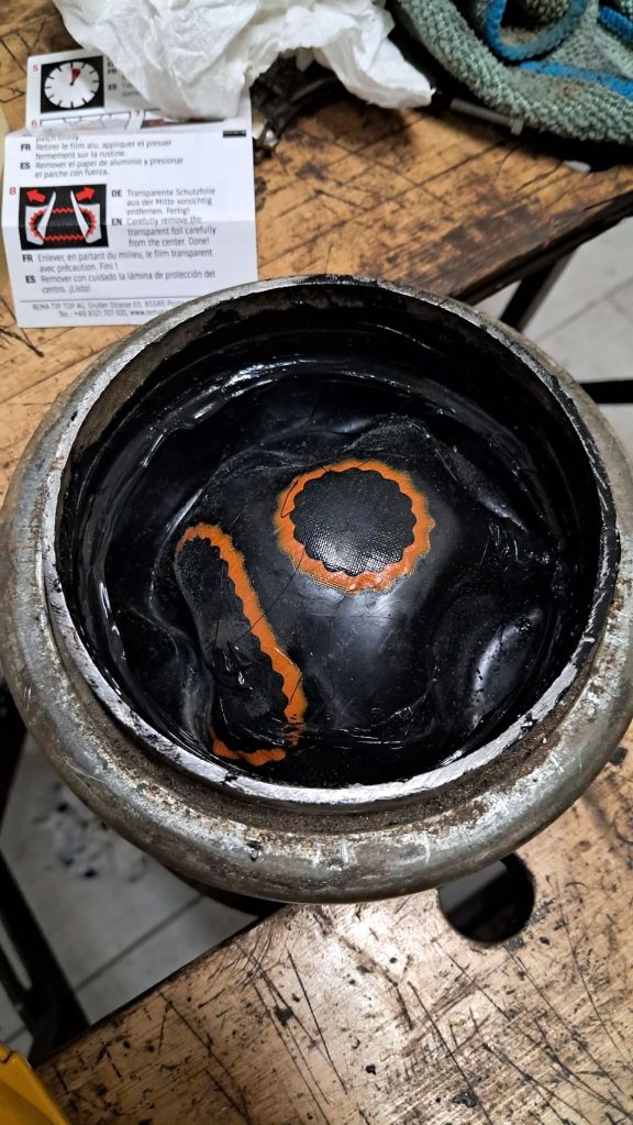
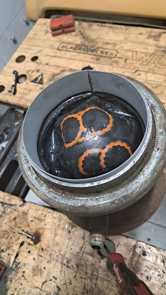
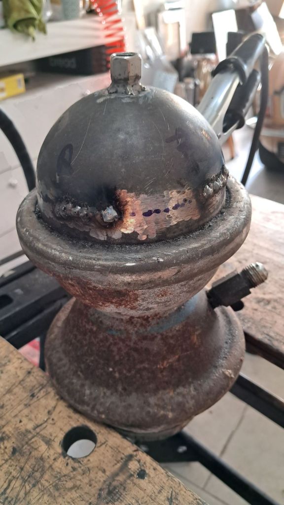
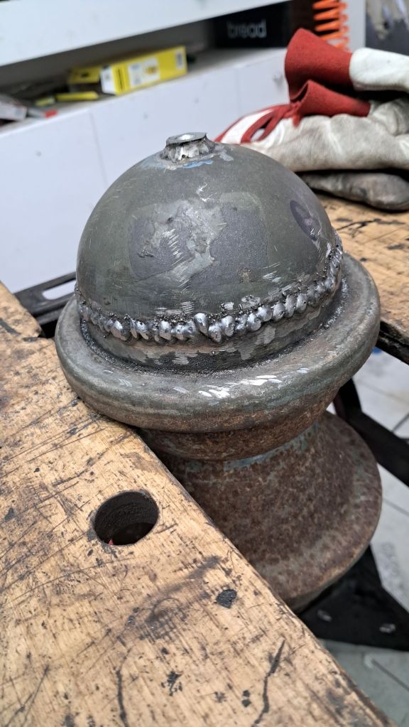
Having depressurised the suspension and removed the displacers I took the opportunity to remove what was left of the old bump stops and replace them with brand new stops. Then it was simply a case of welding the crack shut and welding the hole with the tiniest repair panel I’ve made so far – about 1.5 square centimeters!

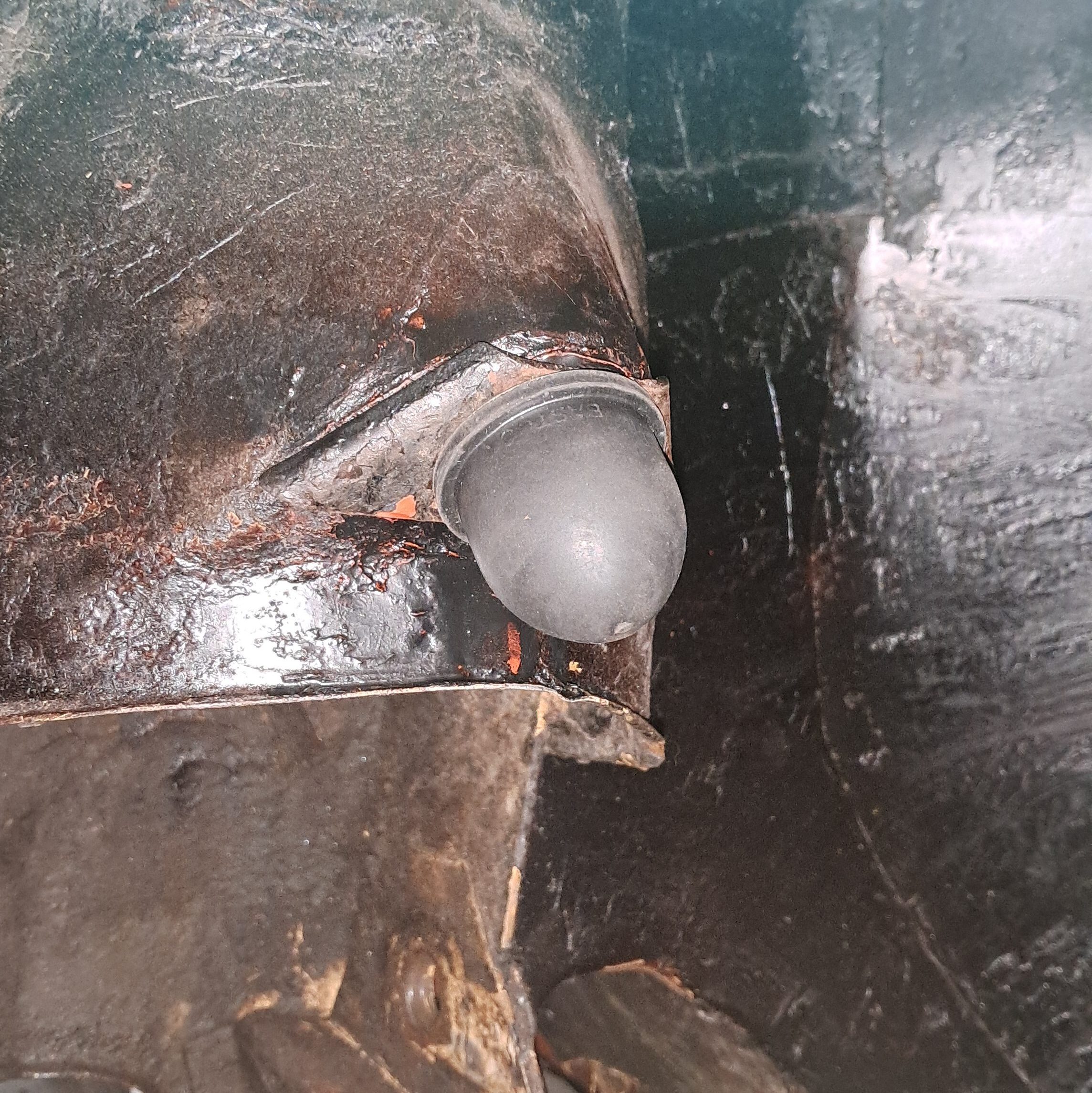
Like an absolute mug I thought I’d got away with it so I decided to clean up the chassis rails, check for any rust and give them a fresh coat of Dinitrol. I had heard the rails were prone to rusting and I was about to discover why: Directly below the suspension towers, the rails are double-skinned. The two panels are pinch-welded together and there is a drain hole drilled through at the lowest point to prevent water collecting inbetween the skins, and this – of course – is where the trouble starts. The passenger side rail has corroded somewhat around the drain hole, in that there is some surface pitting and the skins have a chunky layer of corrosion products growing between them but, overall, it’s solid enough for the time being. Over on the driver’s side, which has always been worse in terms of rust, the corrosion was much more advanced and heading into the “structural rust” paradigm; it had to be repaired.

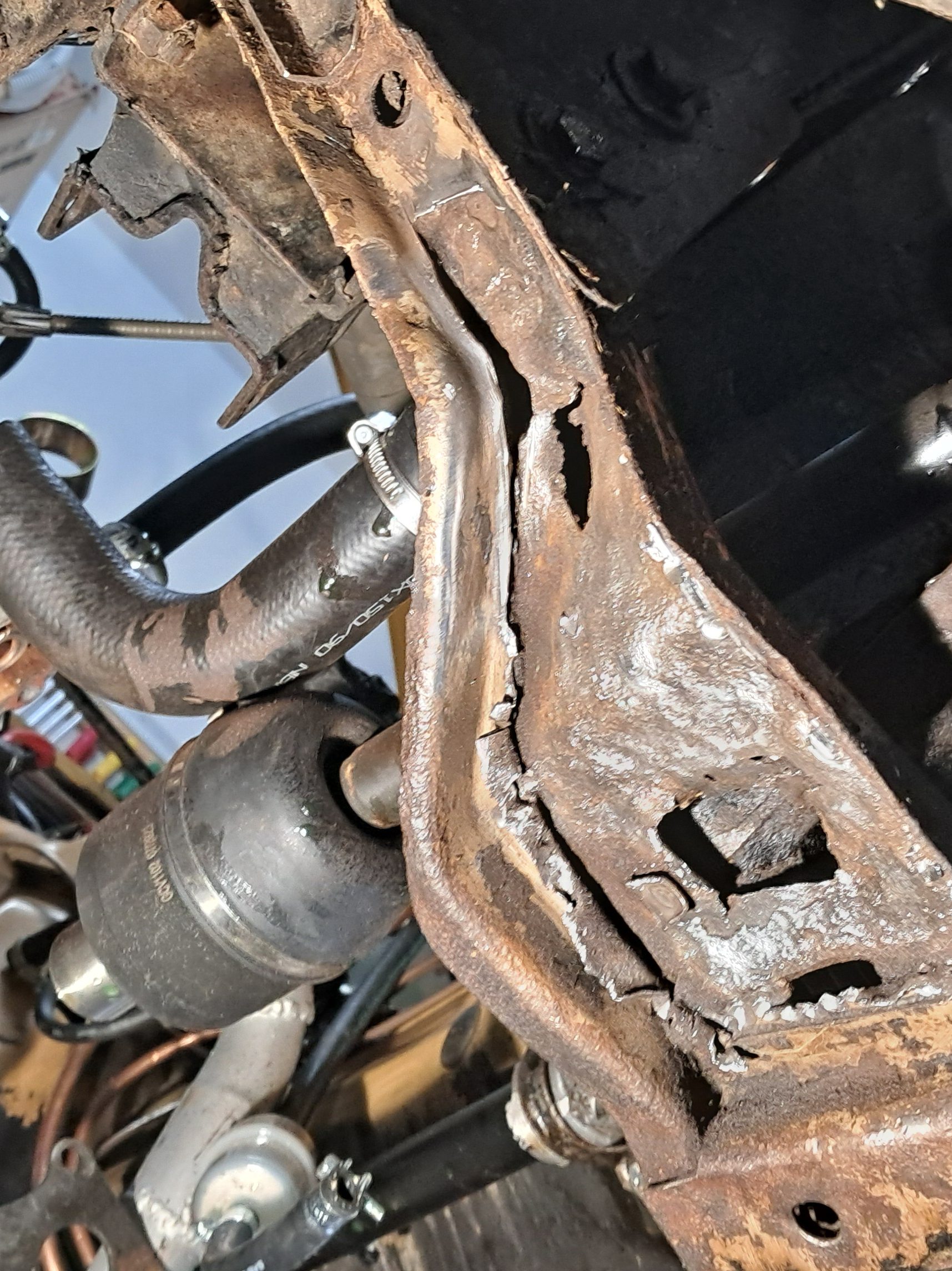
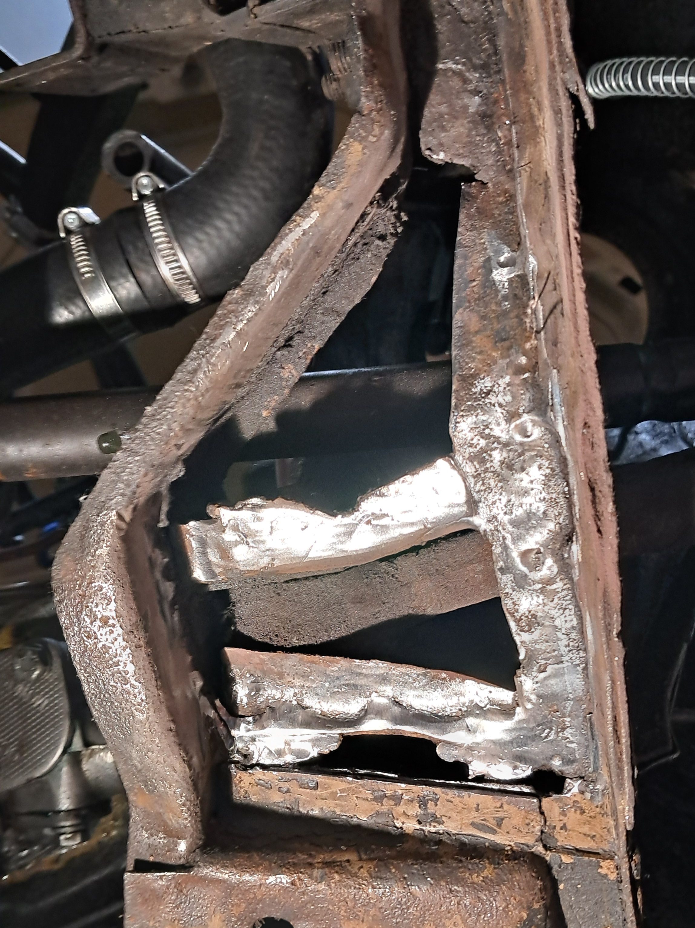
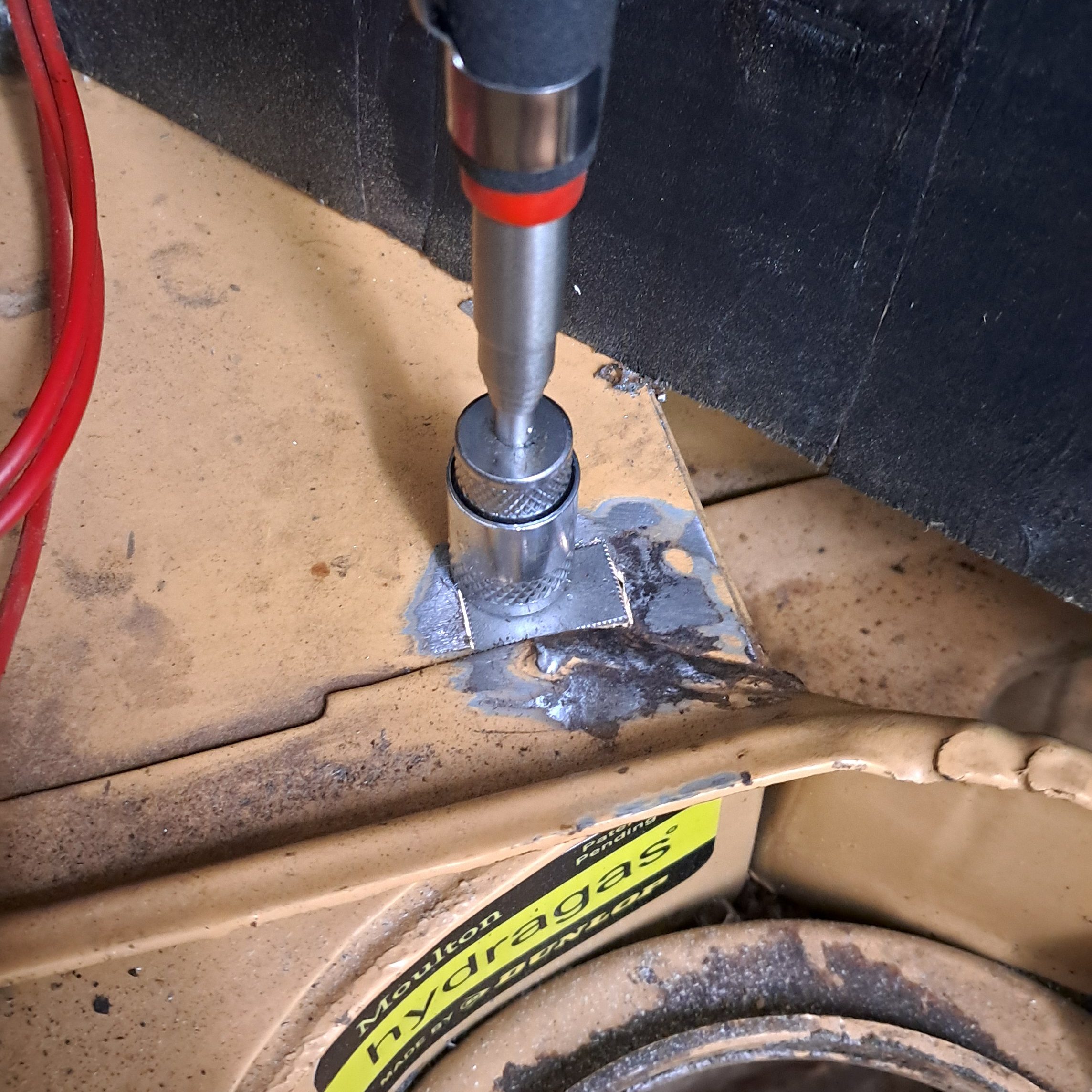
Even with the relative luxury of a QuickJack this was a pretty horrible experience. It’s about as difficult a job as it gets for welding especially for someone with literal hours of experience like me. But the only way to get better at welding is to keep trying and gain experience. So although I’m not particularly happy with the results, I know the rail is solid again and perhaps, just perhaps, I’m a little better at welding now.
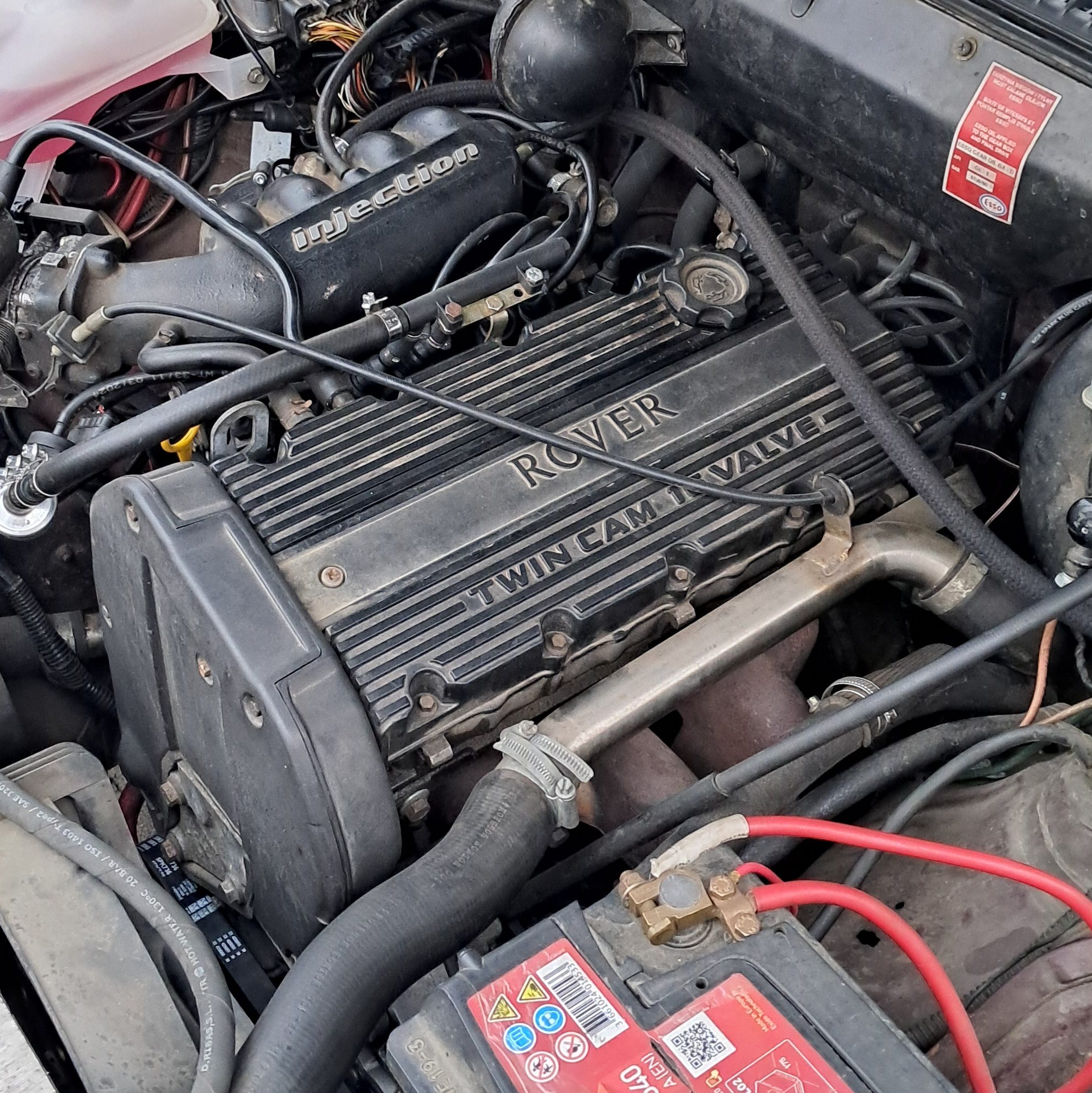
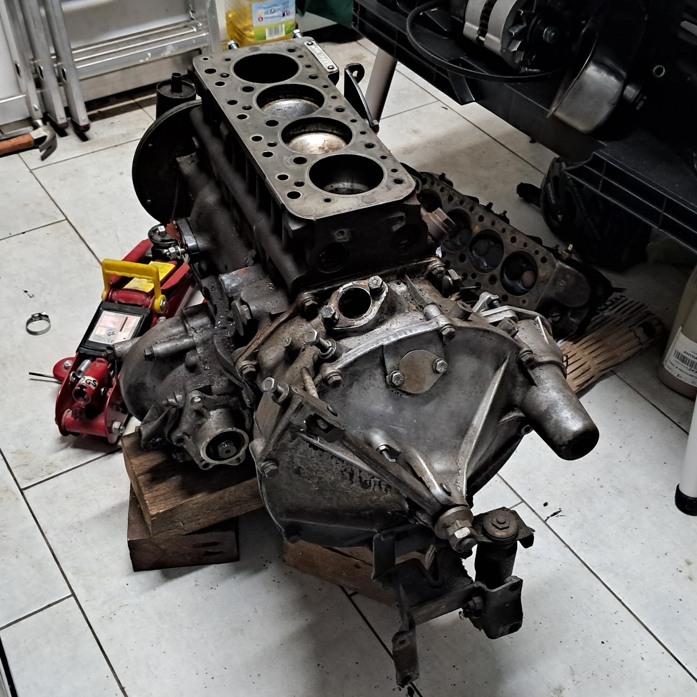
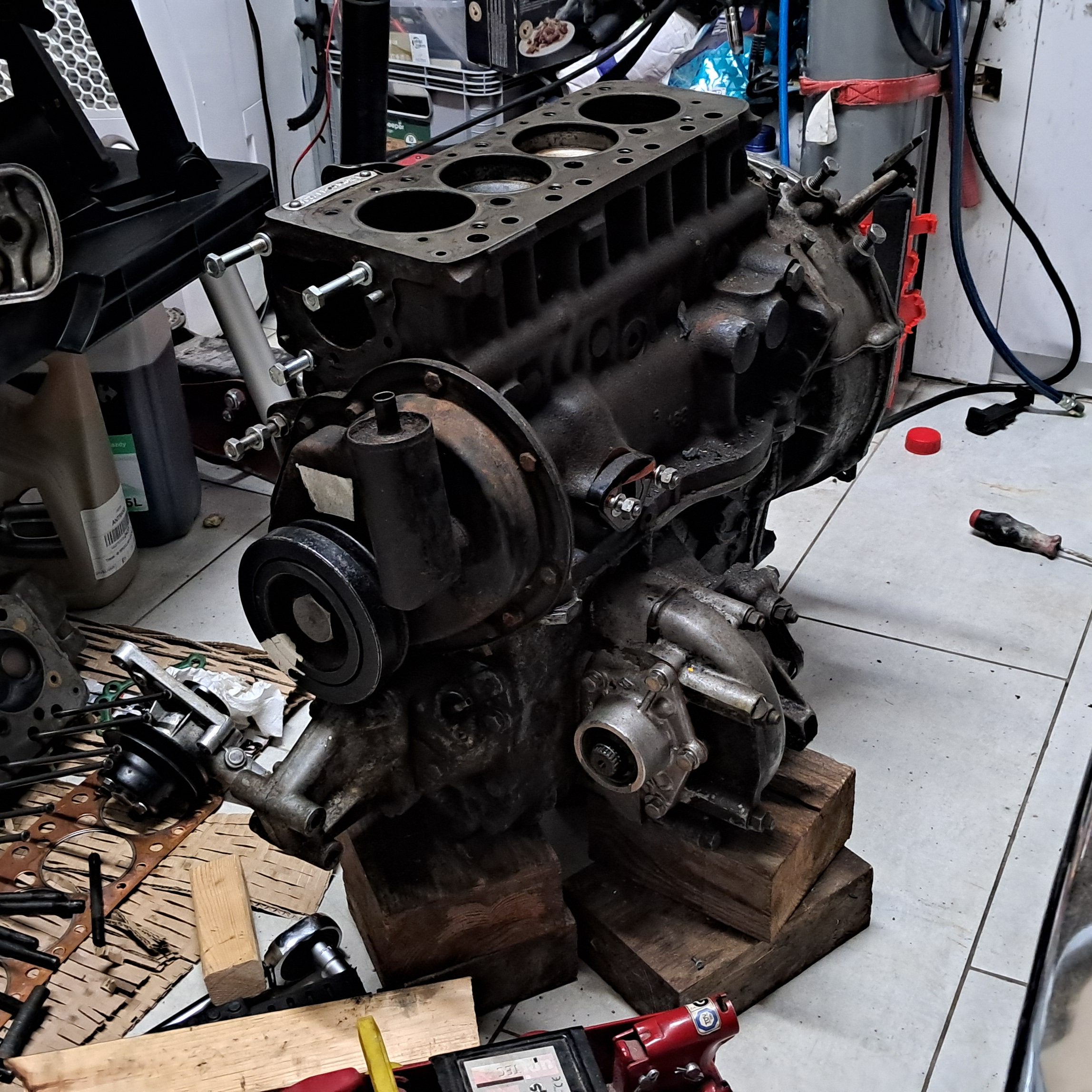
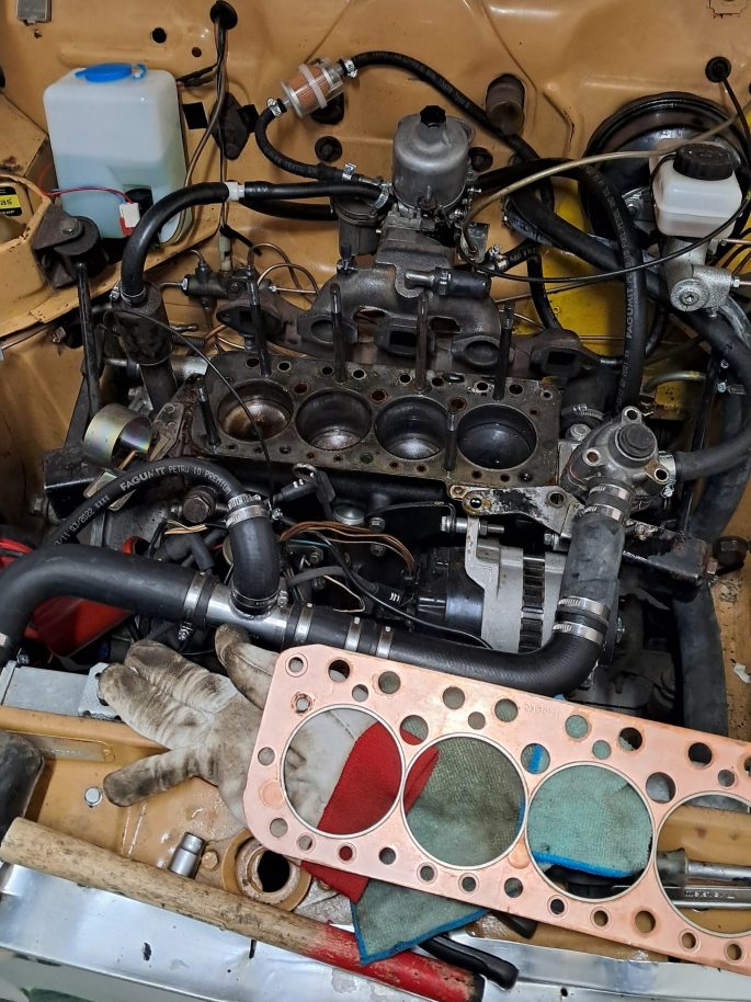
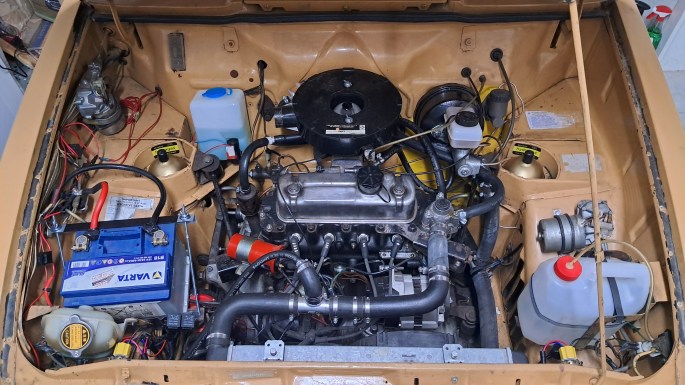
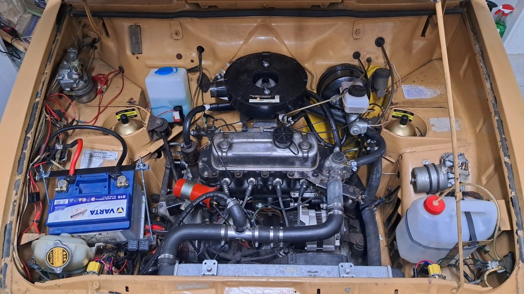
2.2. ENGINE REBUILD

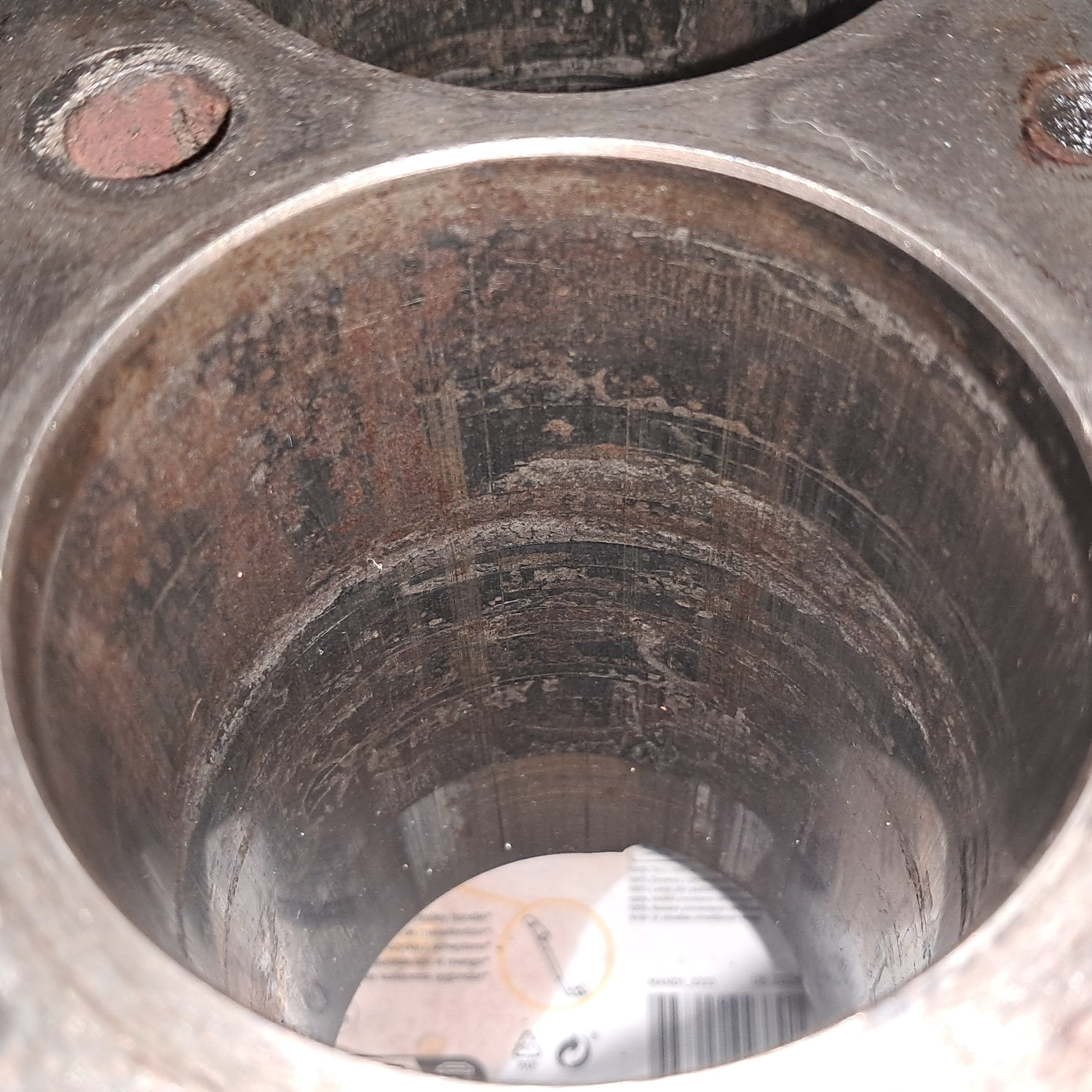
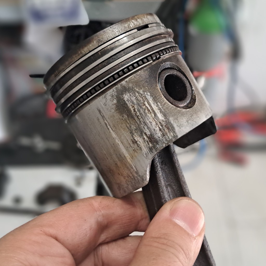
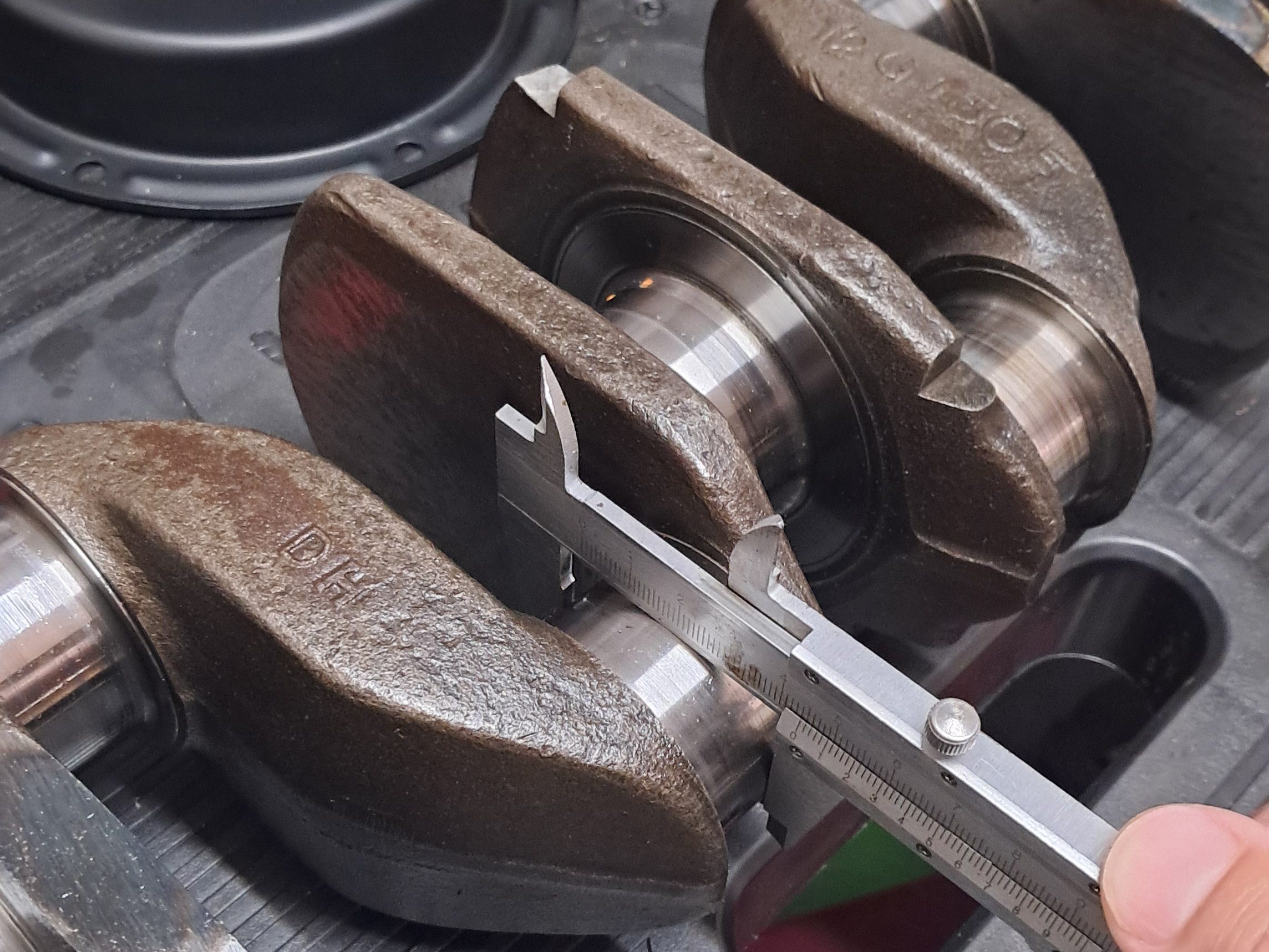
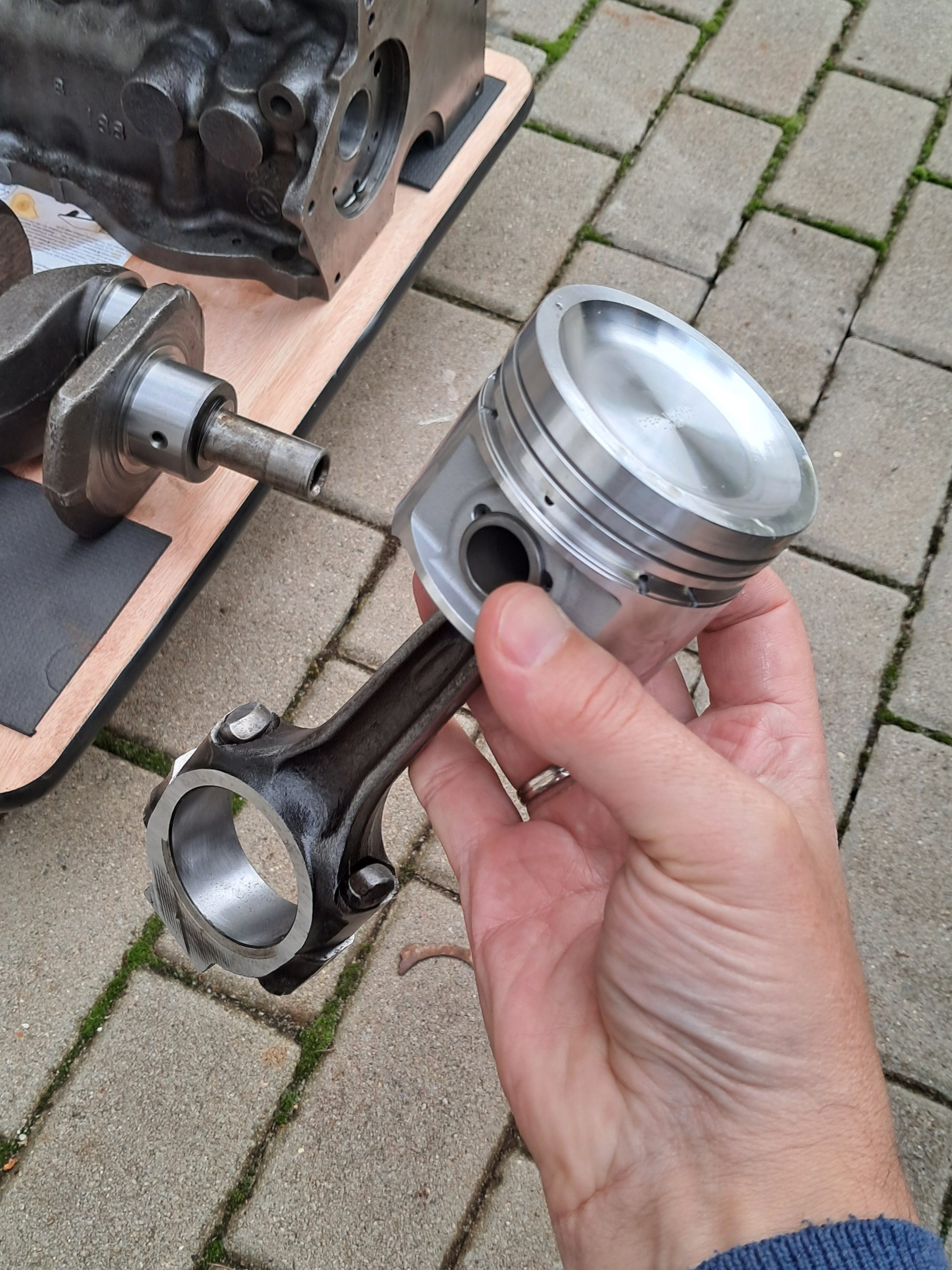
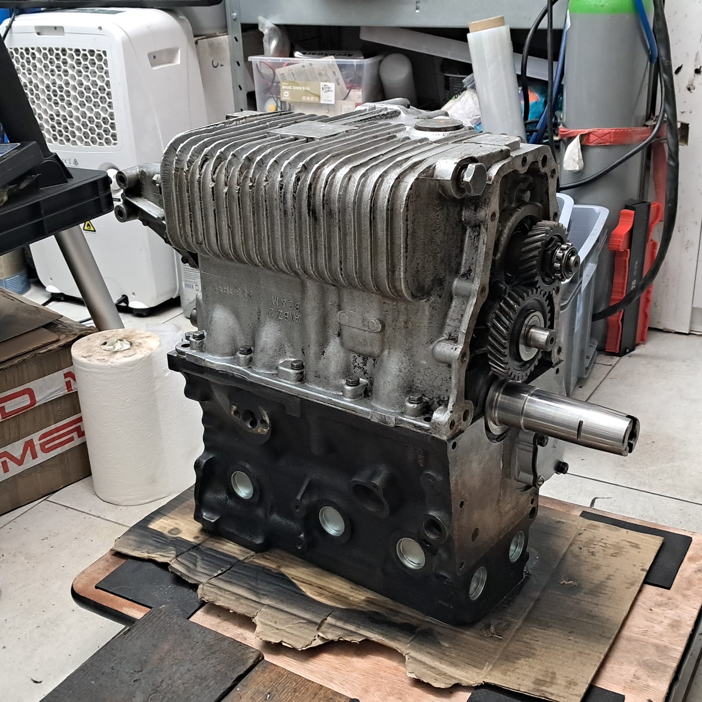
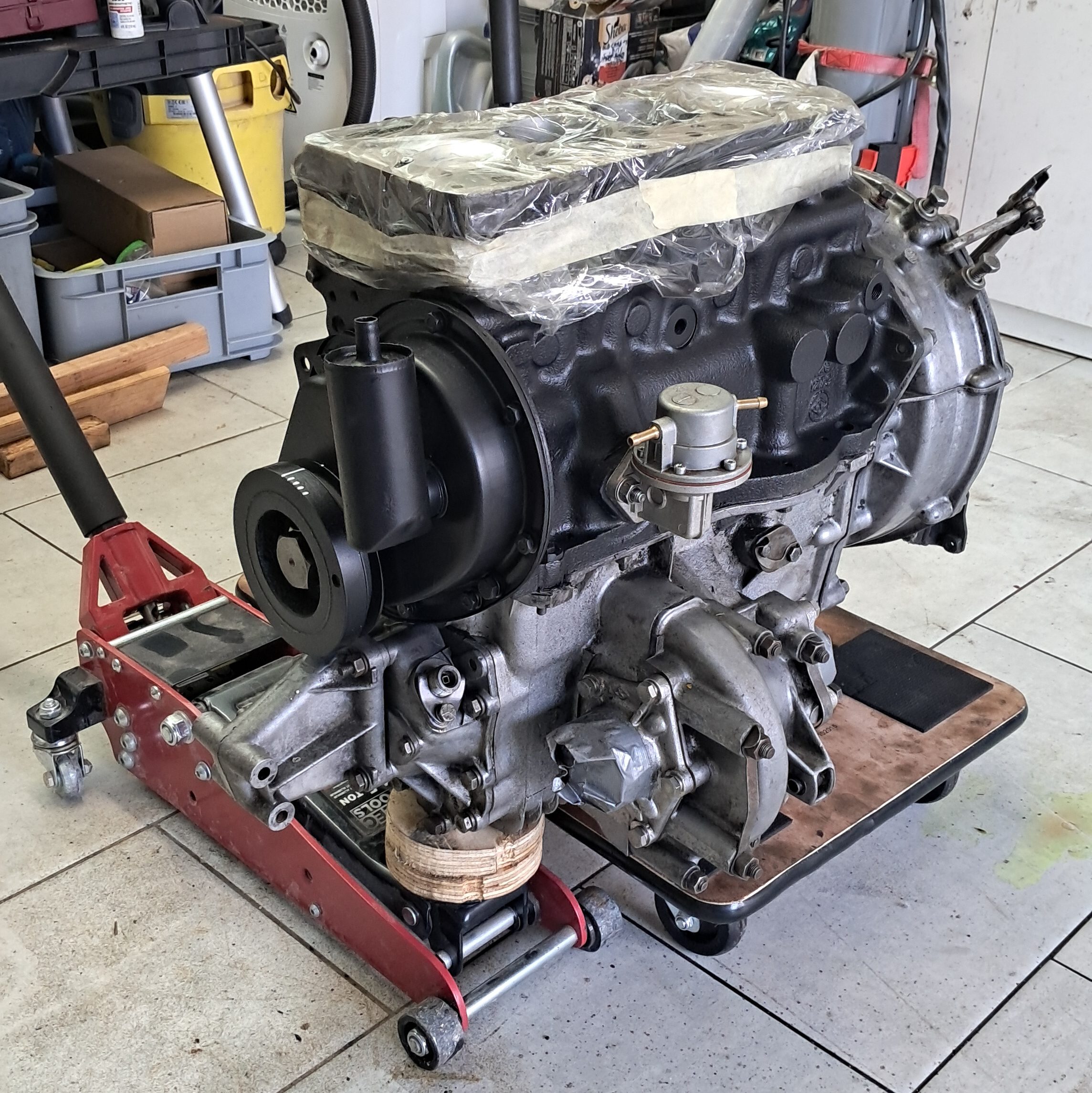
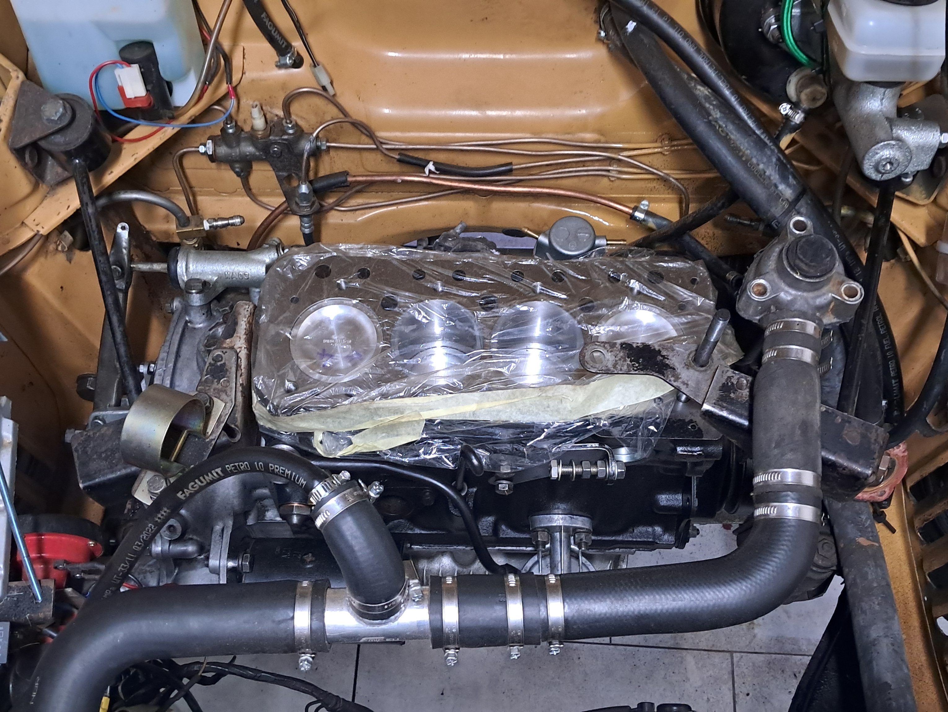
Having got all that horrible welding out of the way, returning to the engine was like putting on a warm pair of slippers. In the previous report Agnetha’s long-suffering A-series had been removed, deconstructed and the block sent to HT for assessment. As soon as the new pistons arrived from MED Race Technologies, and having given the block a damn good pressure-wash, HT got to work on the block and crankshaft. Within a week they had:

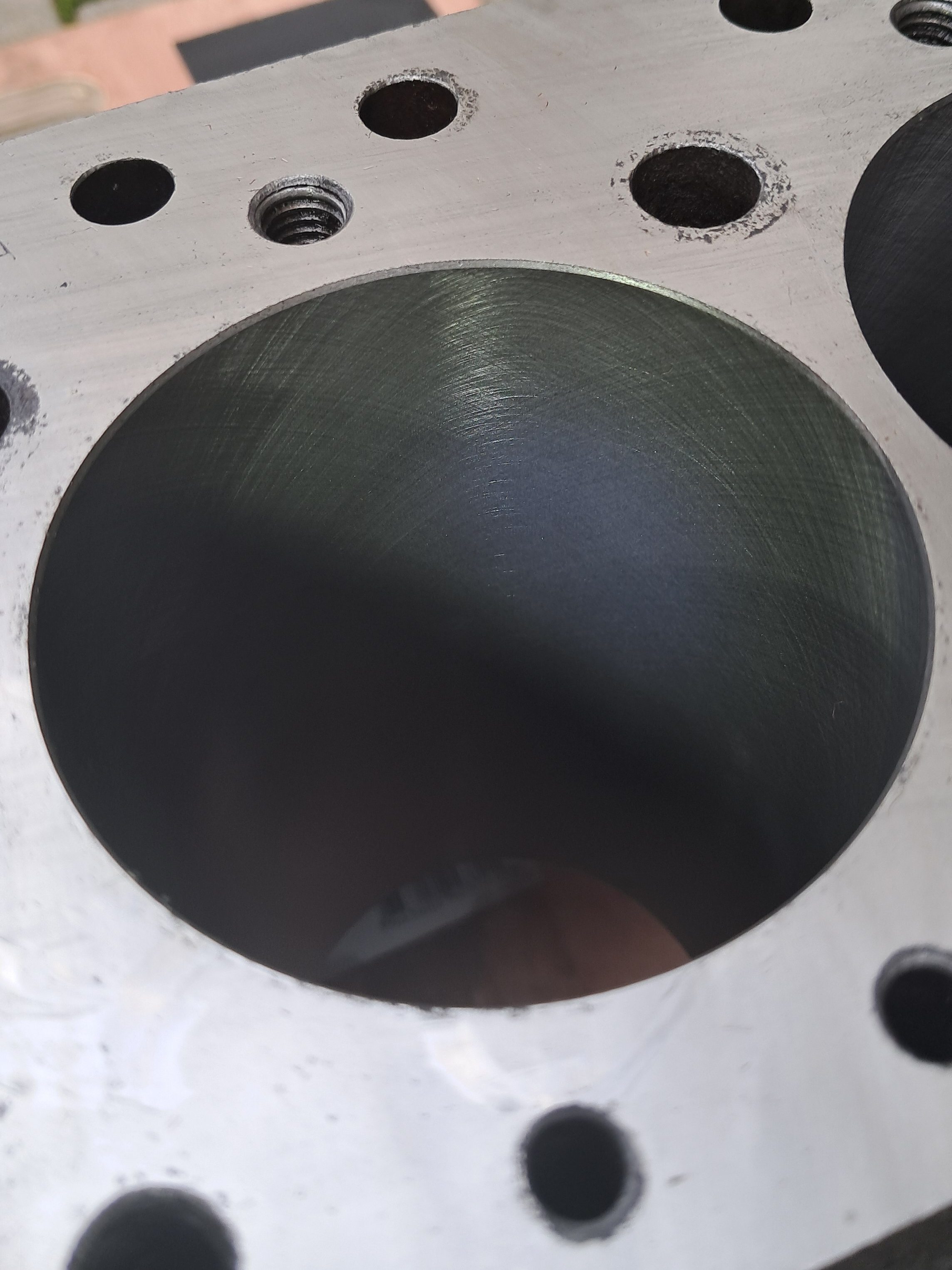
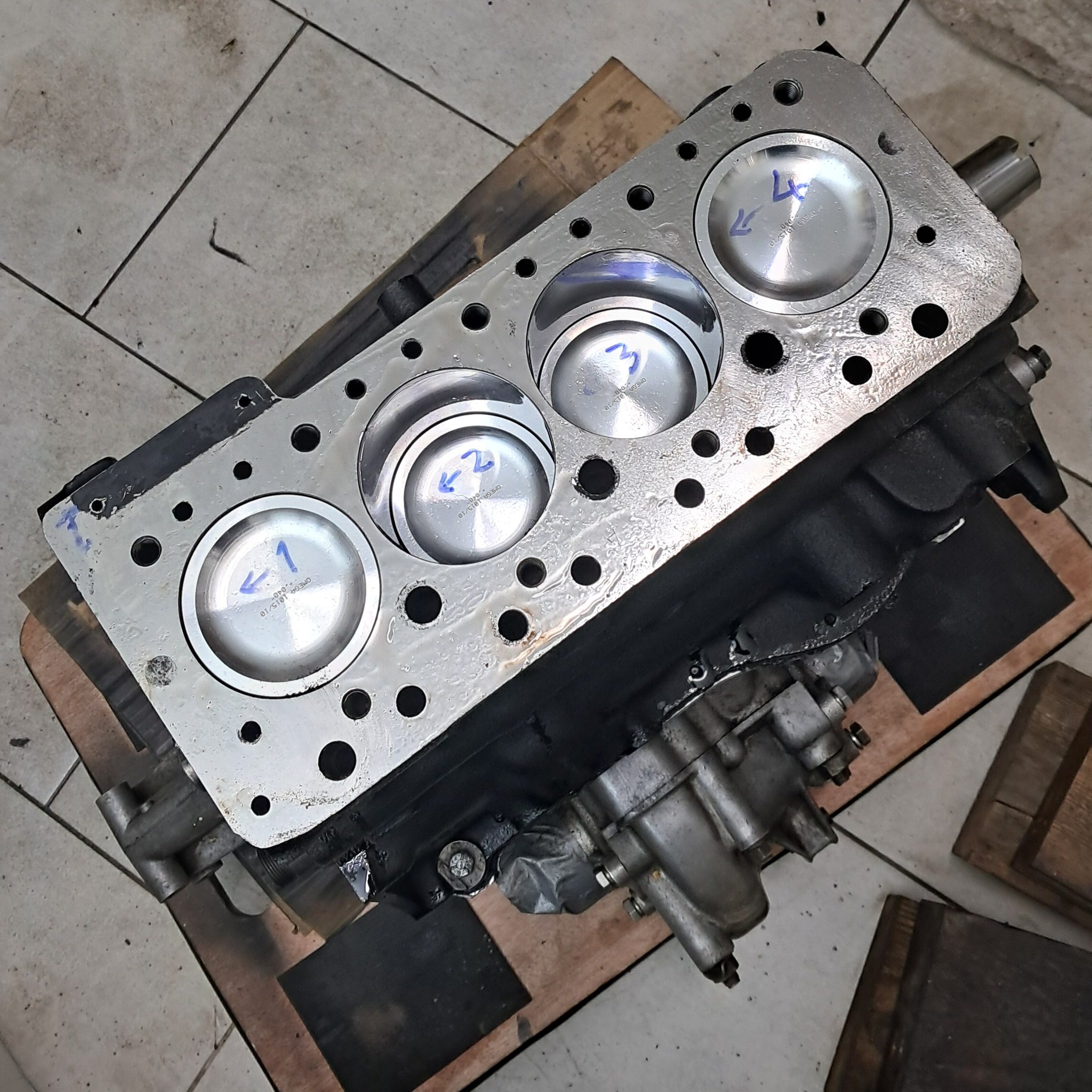
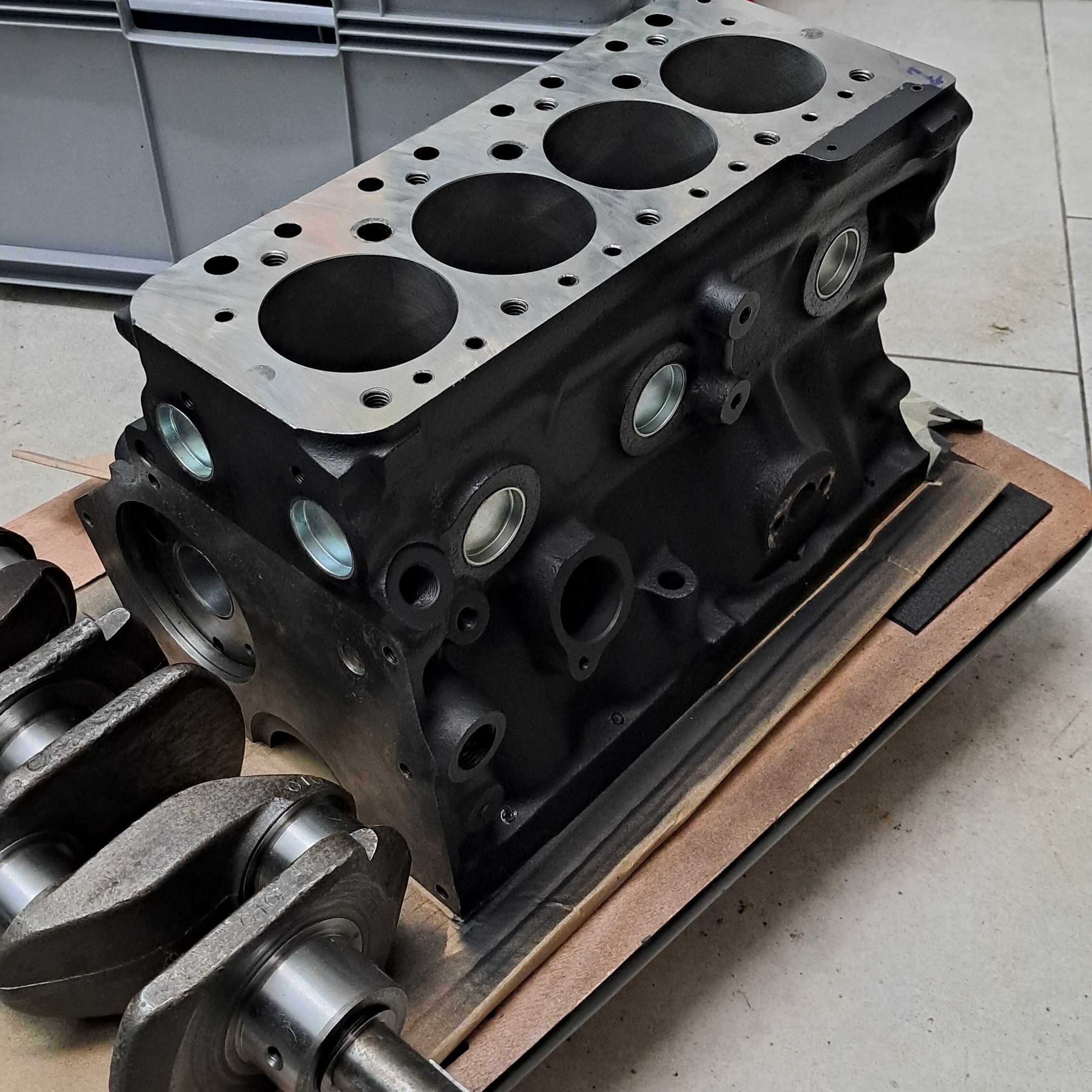
  • Bored-out the block to 1311cc and honed the cylinders.
  • Flattened and polished the top deck.
  • Pressed in new camshaft liners.
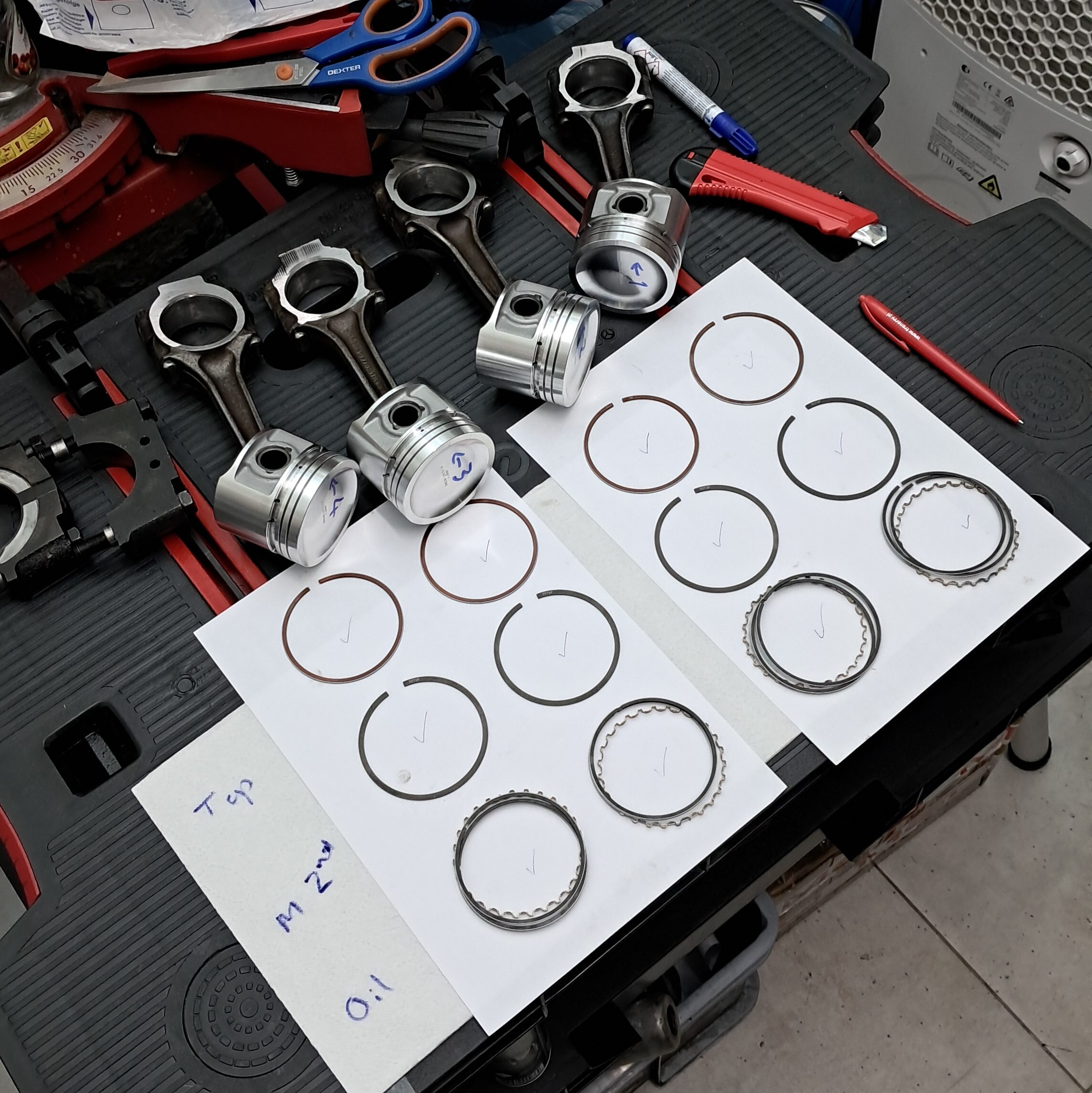
  • Pressed the new pistons on to the conrods.
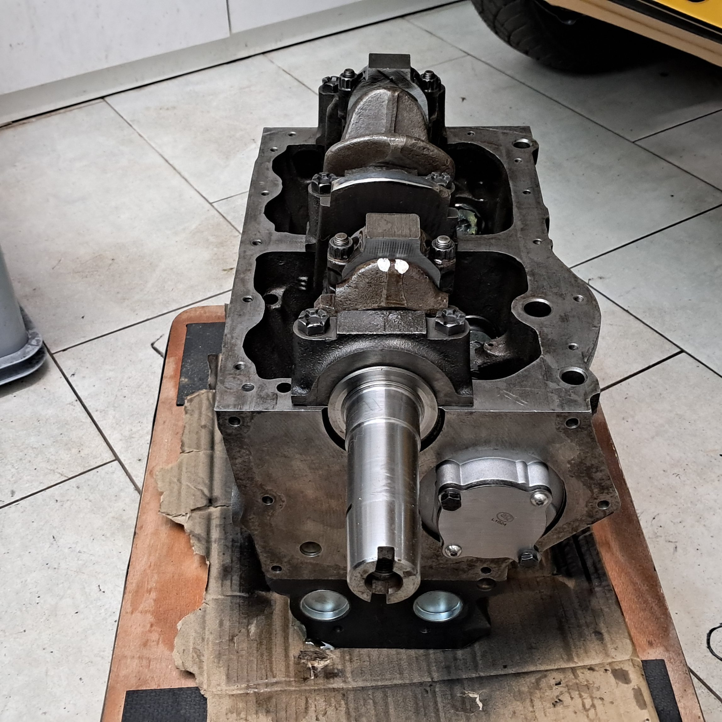
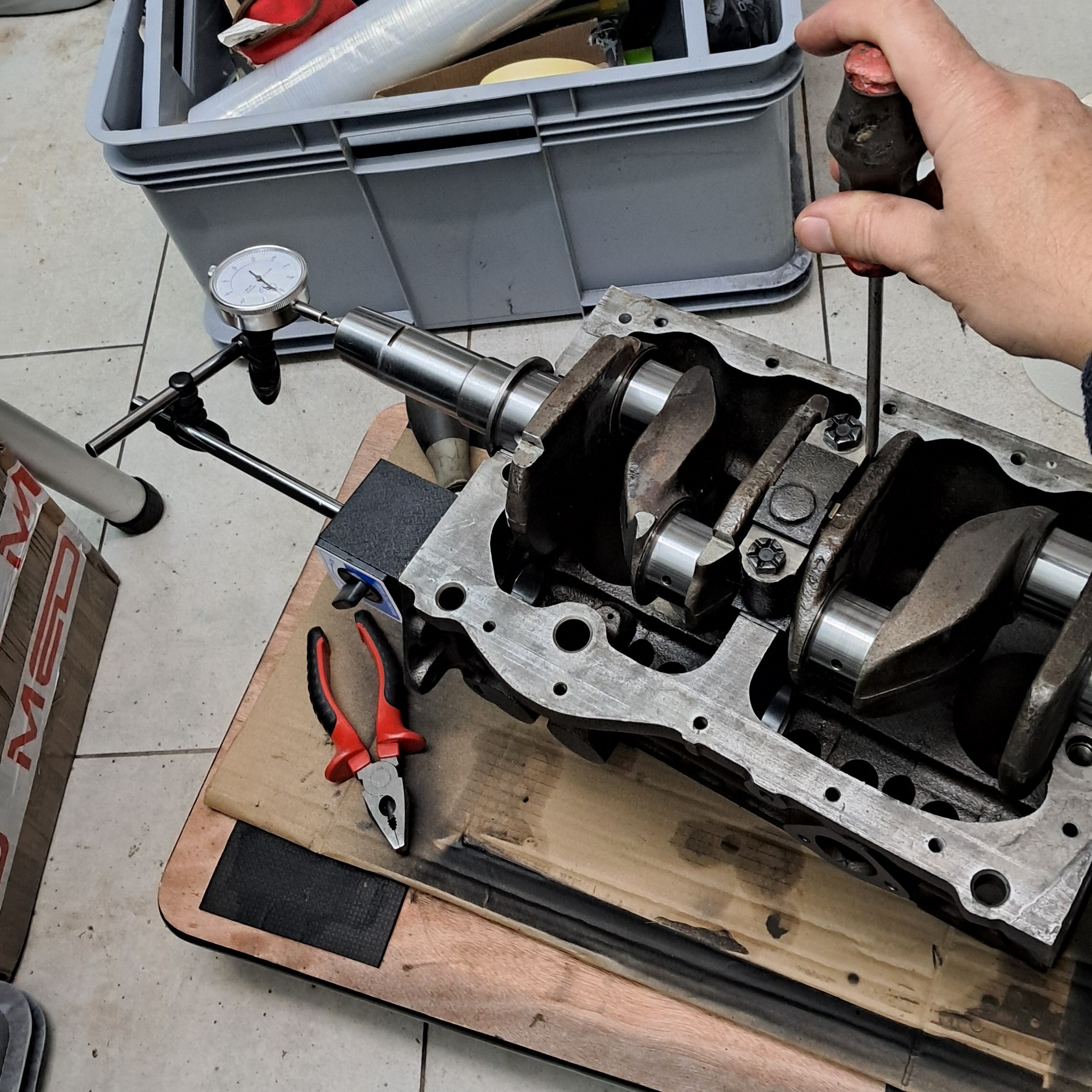
  • Ground and polished the crankshaft to 20 thou.

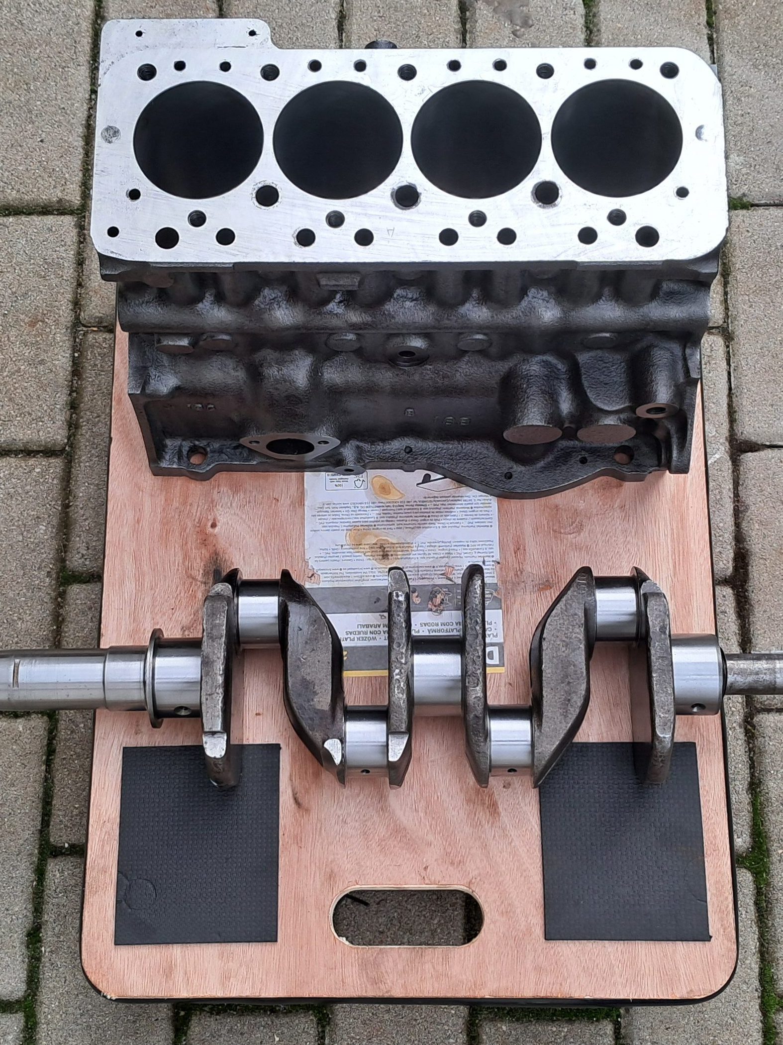
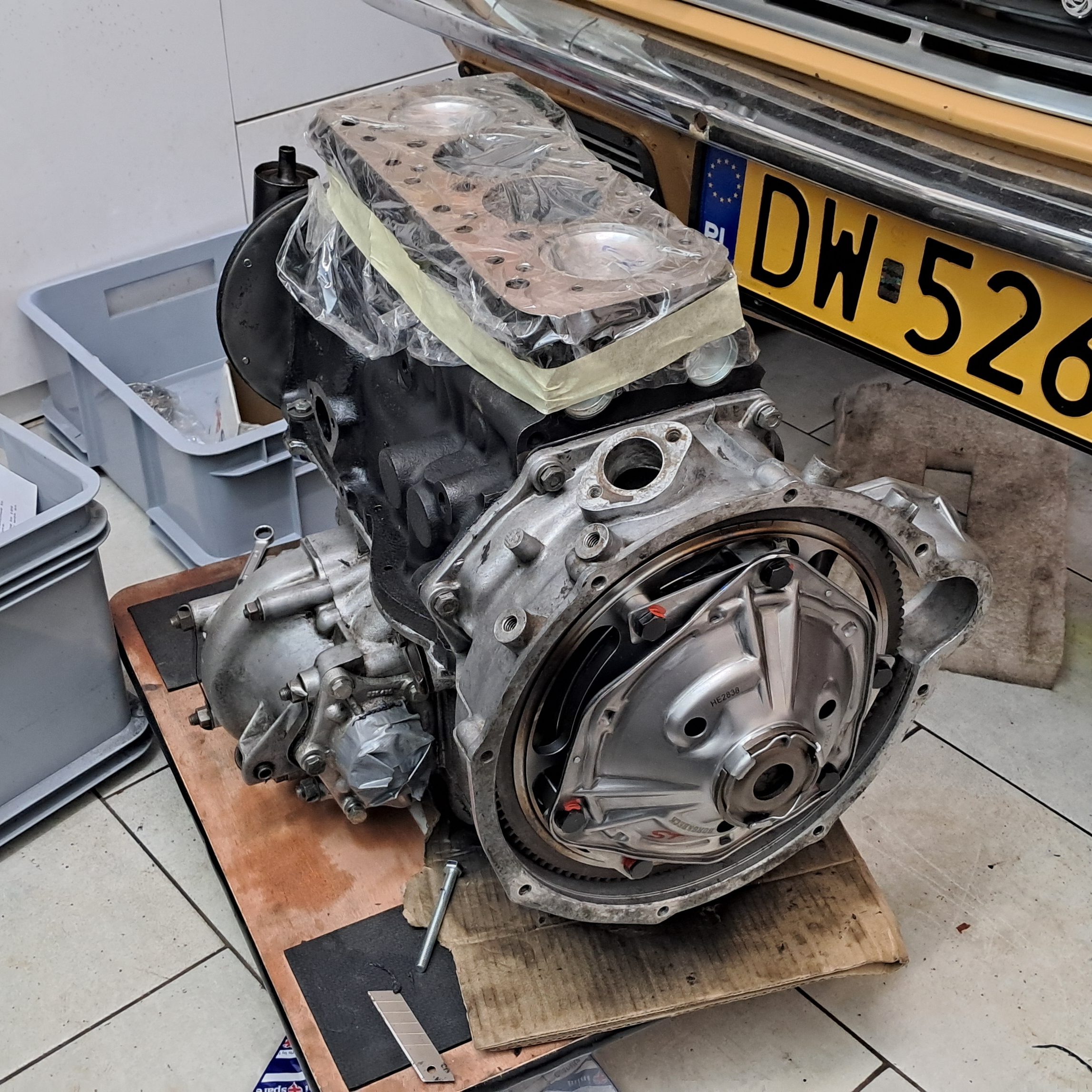
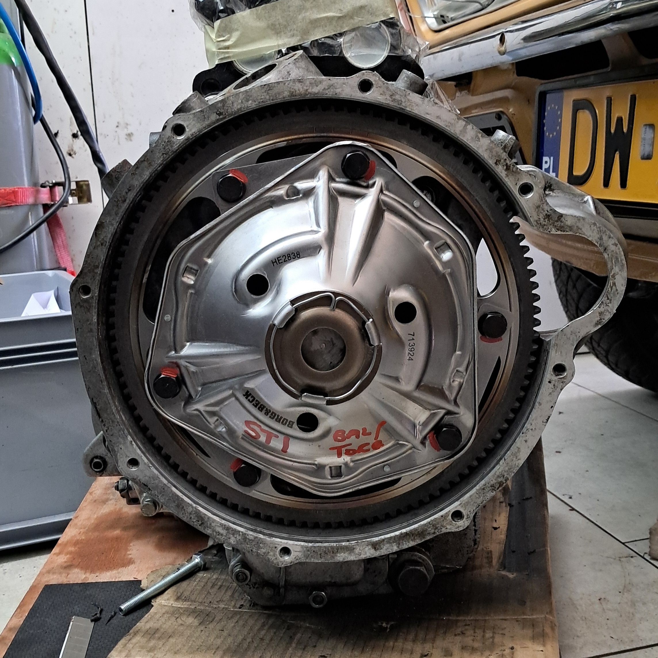
And all at a very competitive rate! Meanwhile I had taken delivery of some “sensible upgrades” from MED including the Stage 2 camshaft kit and, naughtiest of all, the Stage 1 ultralight flywheel and clutch kit. I’m not turning Agnetha into a sleeper but it would be fun to experiment a little with tuning so she can better keep up with traffic. These mods should enable a few tweaks here and there to her fuel economy and power delivery…and I imagine she’ll sound pretty mean, like half a Ferrari (or a 3rd if it’s a 12 cylinder Ferrari)

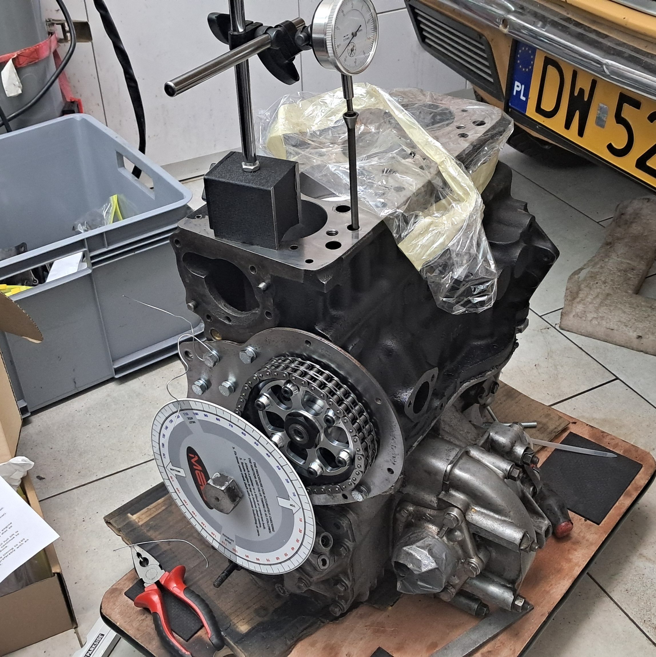
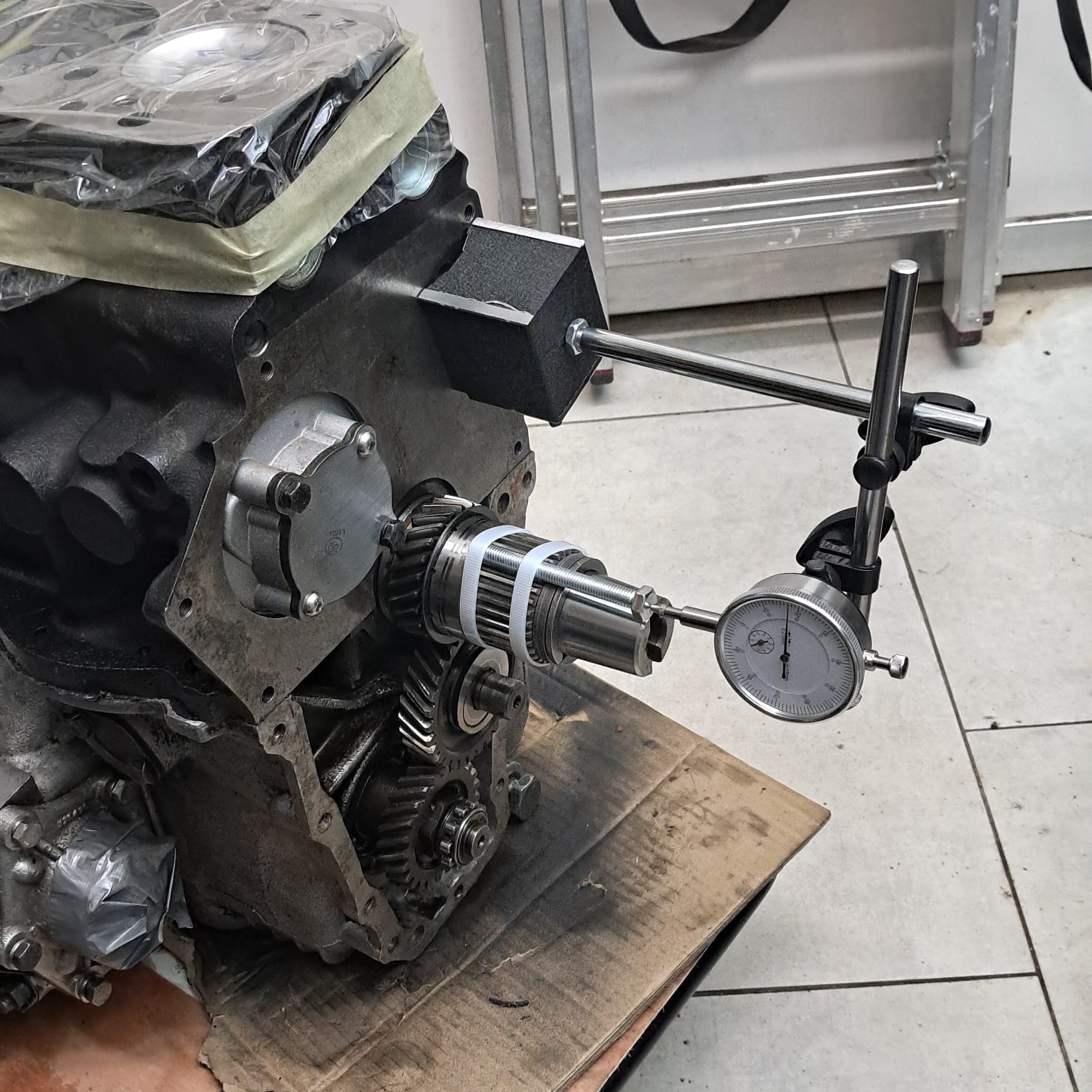
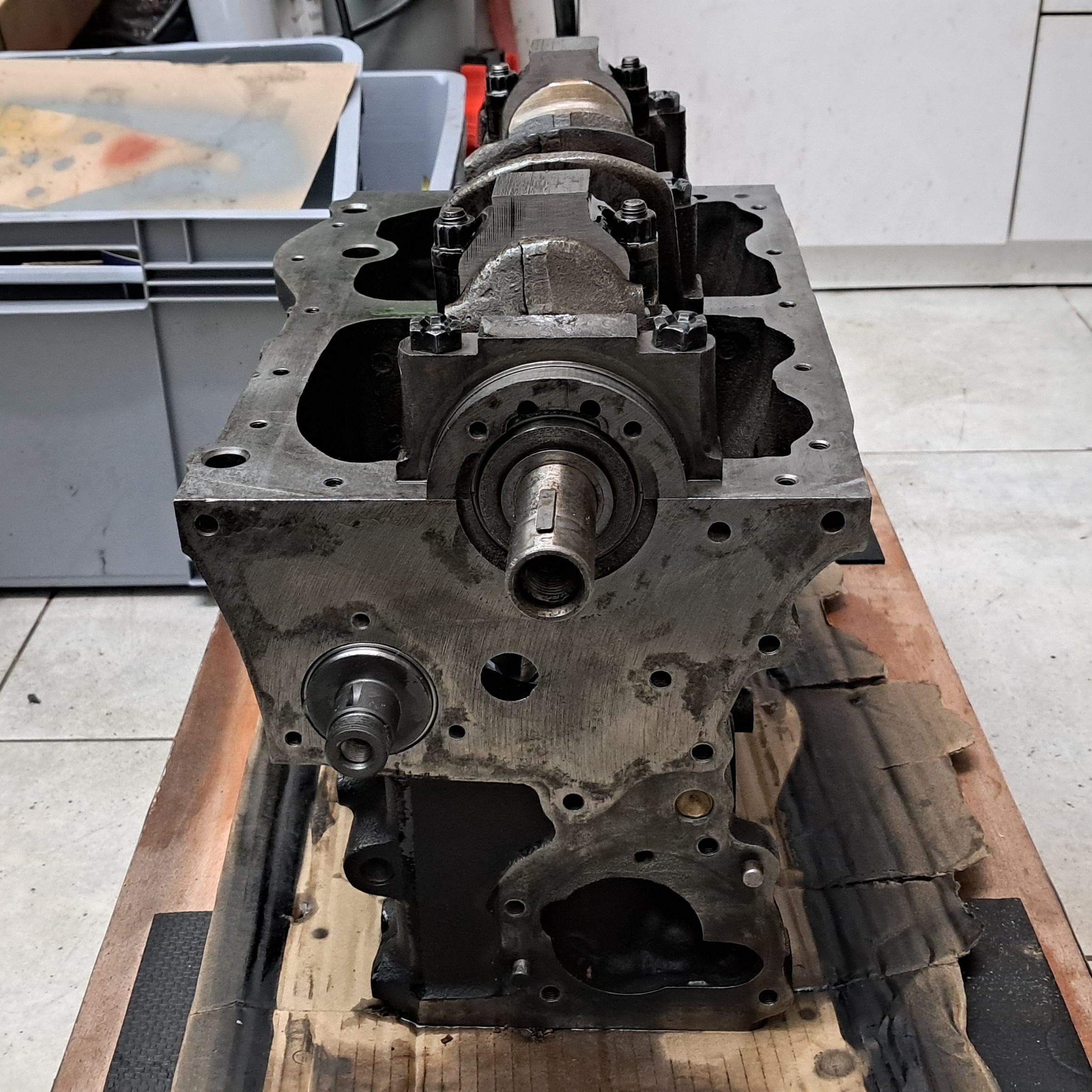
So now it was simply a case of putting the engine back together…how difficult can it be? In all honesty, not that difficult! The hard work is in the machining, since this requires an entire workshop and ideally 40 years of experience. Reassembly, it turns out, is just big Lego, some careful measurements and a bit of grunt every now and then. I found this YouTube playlist to follow along step-by-step and in the end I was very pleasantly surprised with how easily the engine fitted together (again, this is all down to the machine shop) and that everything was back to well within factory tolerances.

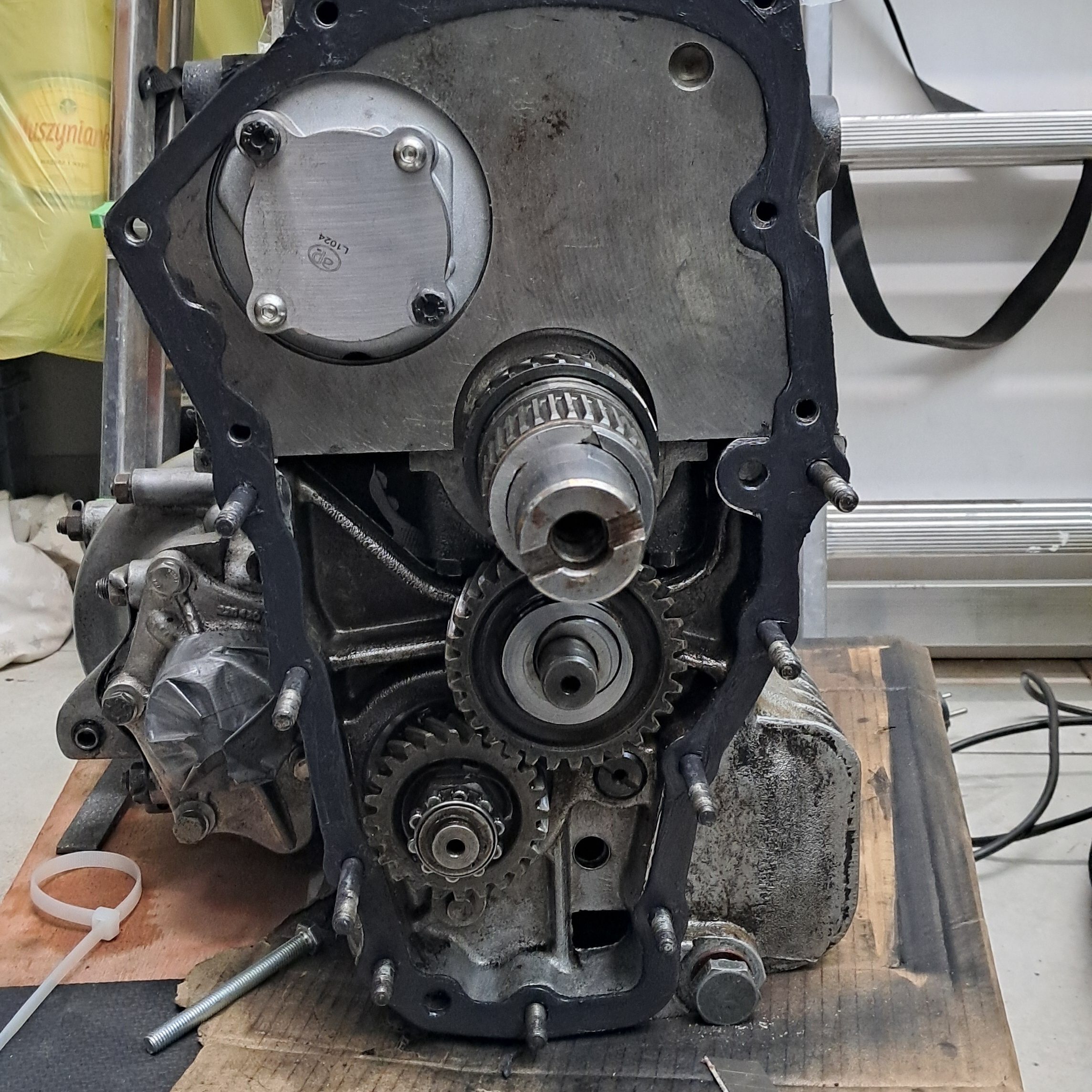
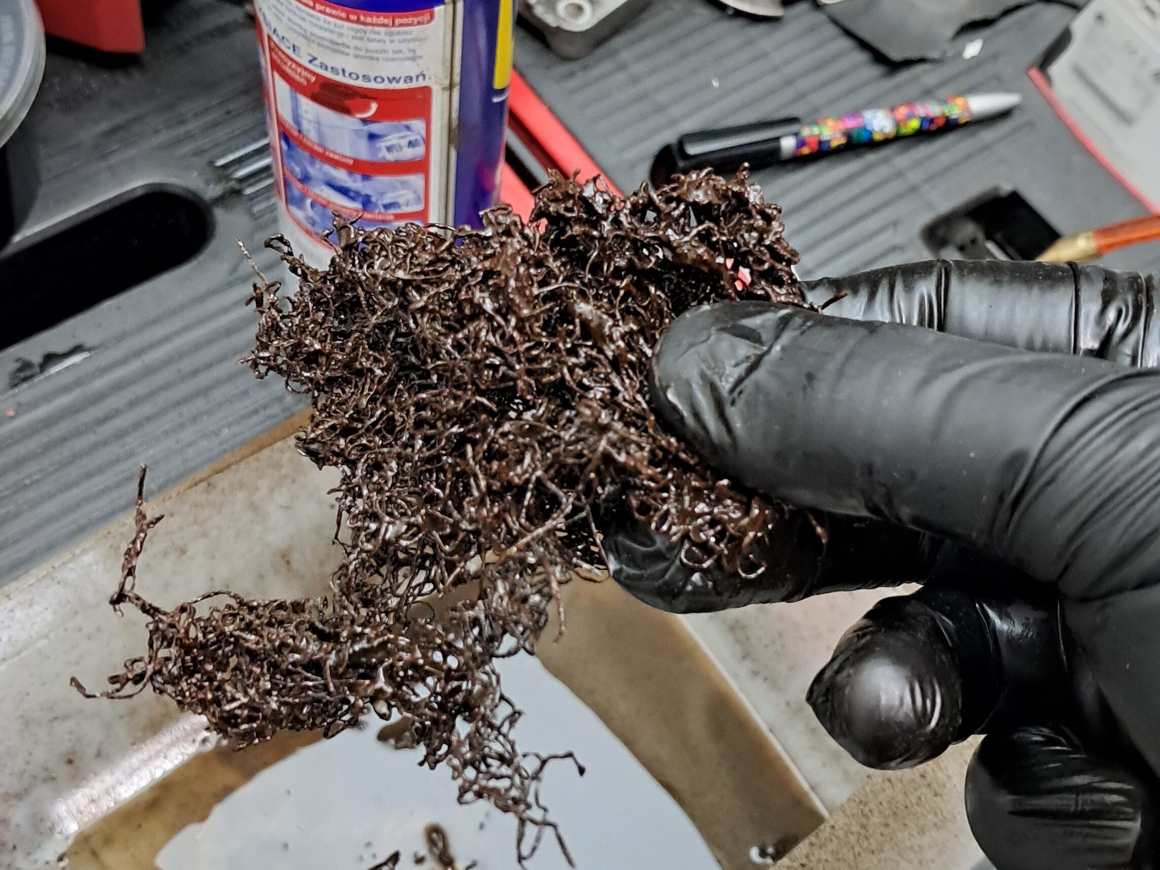
A small detail I picked up from the playlist was to gut and repack the flame traps. I imagine this is often overlooked. It’s a pretty gross job to remove the packing but once flushed out with WD40 it was straightforward to repack them with a pan scourer each – just make sure they’re steel pan scourers and not coated plastic!

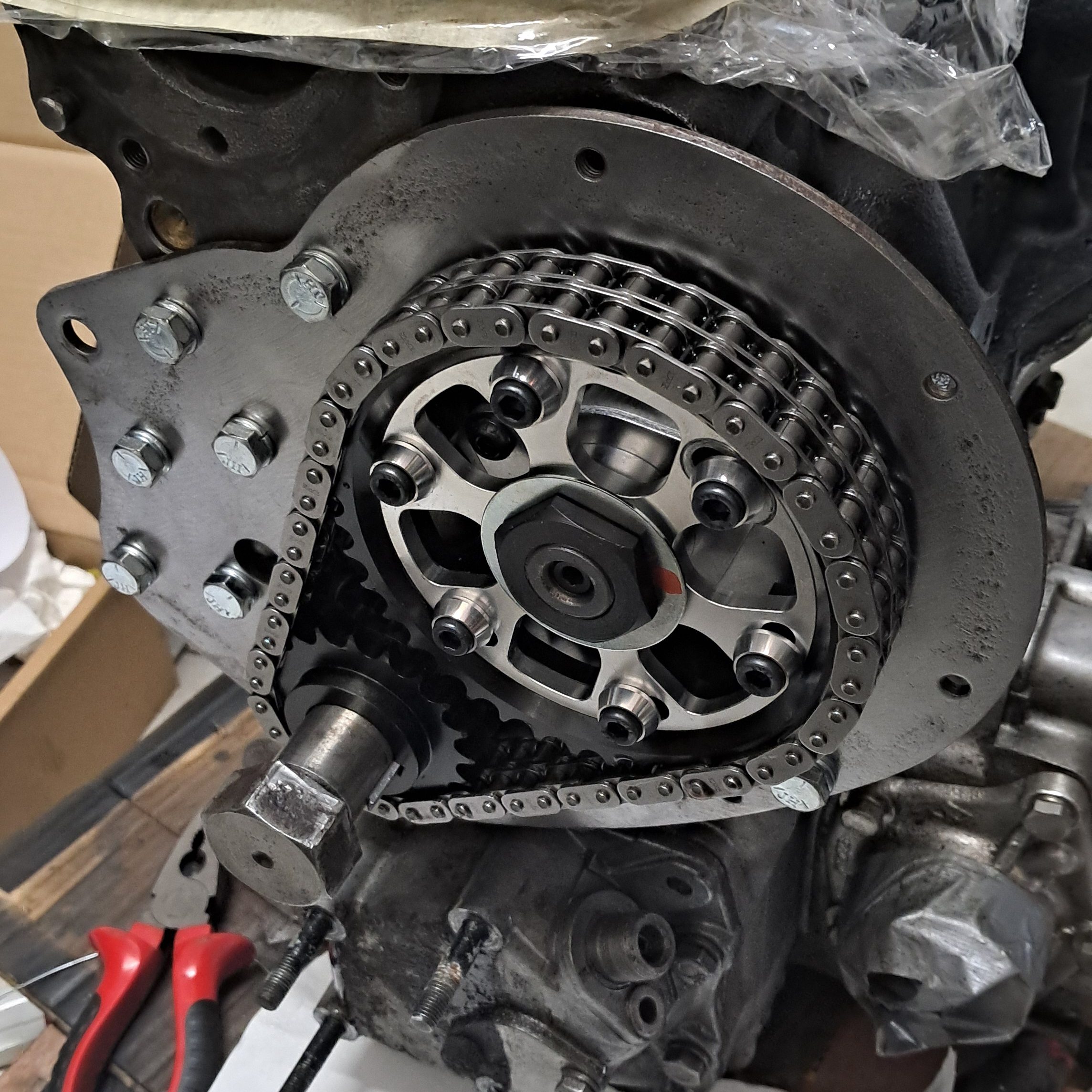
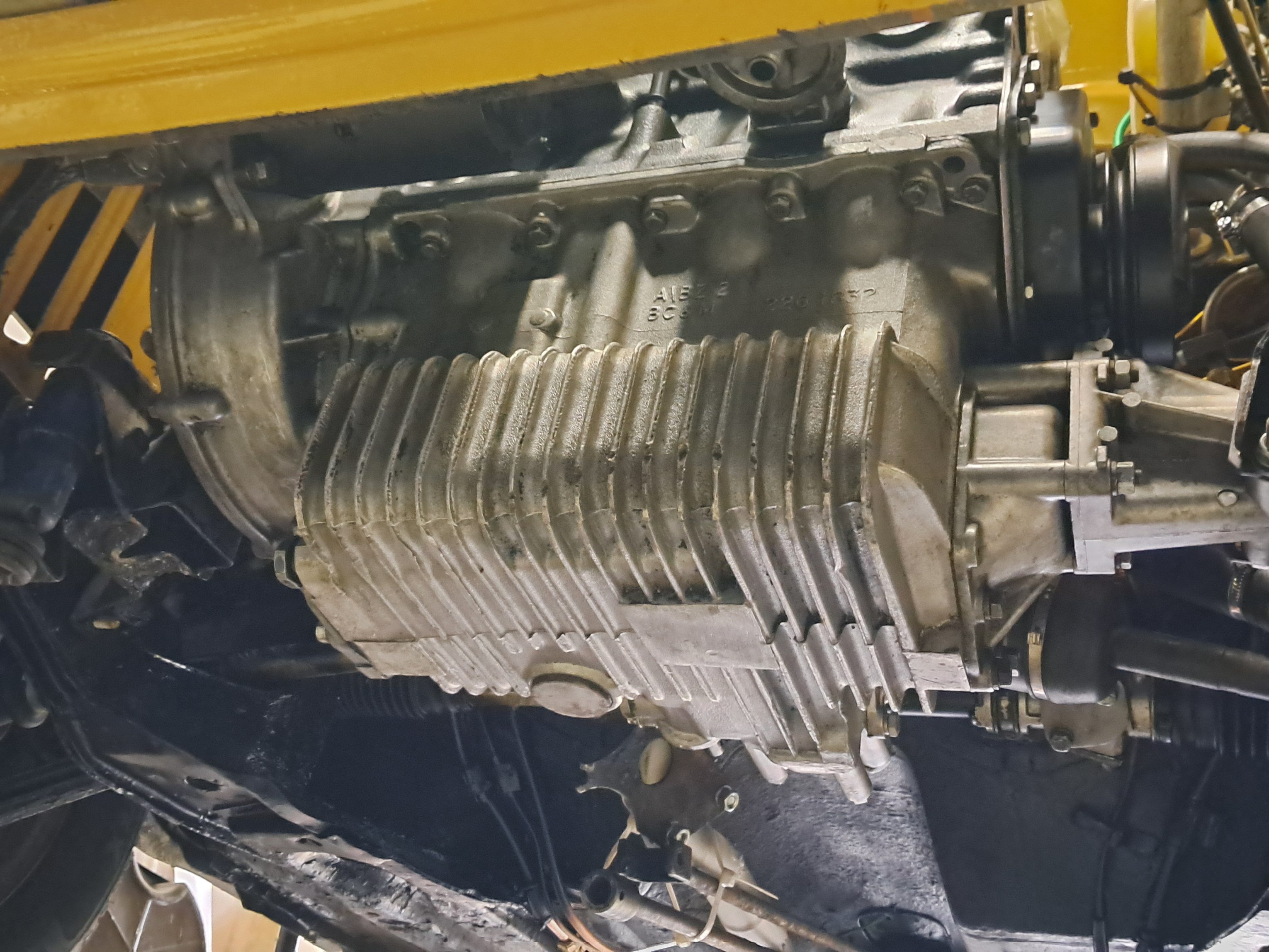
Another detail that can, apparently, end in catastrophe if overlooked, was to replace the damper pulley on the crankshaft. Back in the later neolithic period, when a Mercian tribe lead by a druid monk name John Cooper realised the full potential of the BMC A-Series by building the first 1275cc engines, it was quickly discovered that the crankshaft has a tendency to ring like a church bell at about 5000 rpm and resonate the bottom end into a thousand broken pieces within a few seconds. Not ideal if you get caught out overtaking a ox-drawn cart laden with stone monoliths. To counter this, the crankshaft pulleys on 1275cc engines have a dual purpose: primarily to drive the water pump and alternator but just as importantly to prevent the dreaded 5 kHz resonance. To do this, the pulley itself is bonded by rubber to a steel wheel (the damper) so that any vibrations from the crankshaft are absorbed by the rubber and the damper, preventing the crankshaft from resonating.

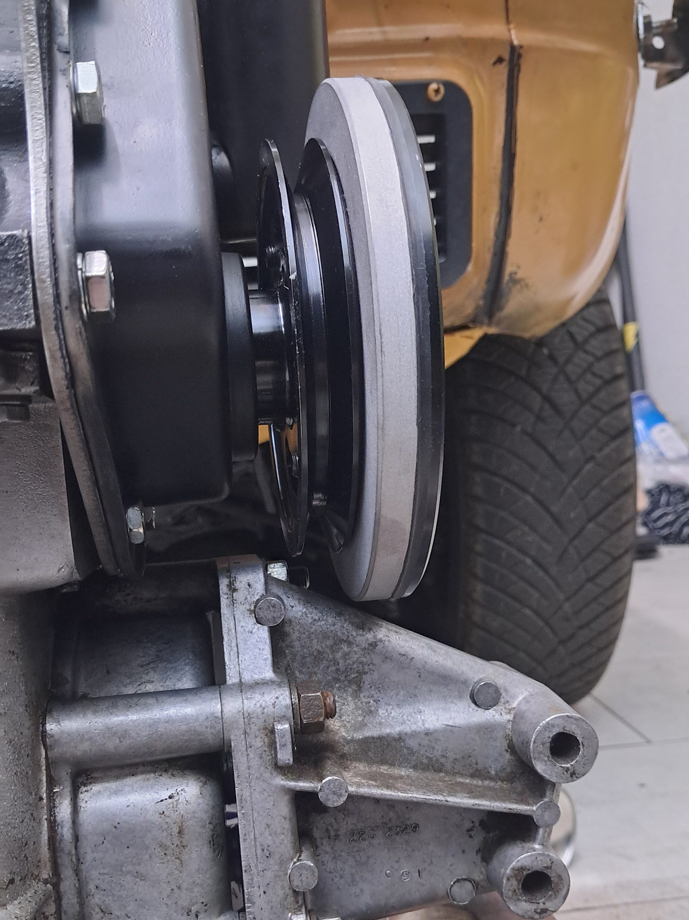
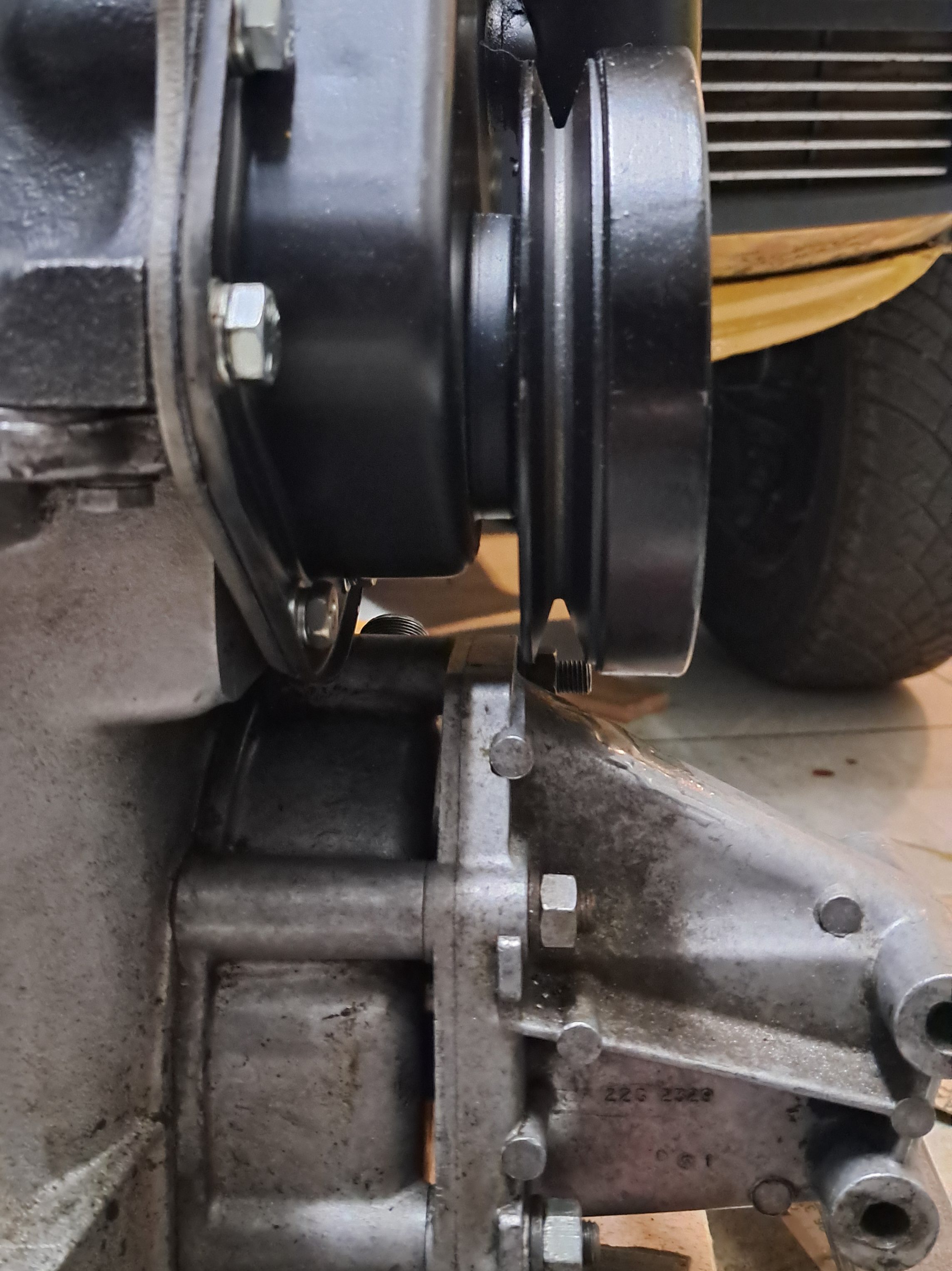
The downside is that the rubber is known to perish after many years and, being deep in the engine bay, is difficult to inspect. Degraded dampers have been known to shatter and explode, taking the crankshaft, bearings and bonnet with it. So it’s a good idea to replace them every few decades. Unfortunately the S-pullies favoured by Mini enthusiasts do not fit the Allegro (I tried!) due to the engine mount immediately below the crankshaft fouling the outer edge of the balancer. This had me in a bit of a fix for a moment since I couldn’t find any Mini specialists that stocked the standard pulley, but thanks to a suggestion from Google Gemini I quickly realised that most MG specialists tend to stock them.

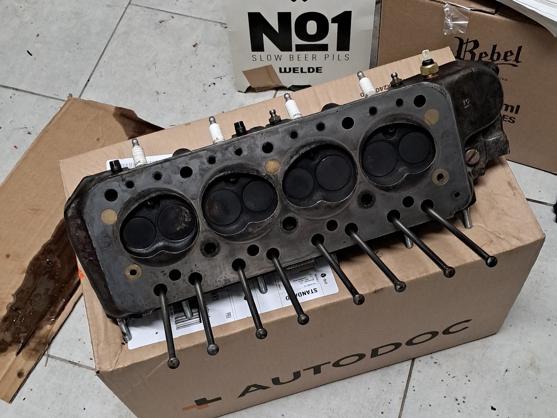
Finally, the cylinder head. I did a partial overhaul early in Agnetha’s recommissioning in 2023 with a general clean-out, new valves and new springs. However the valve seats were clearly in need of re-cutting and the exhaust seats were still the softer type for leaded fuel (it also looks like the exhaust seats were already beginning to melt!) With that in mind I’ve outsourced the head to another workshop for the full enchilada:

  • Recut the inlet seats
  • Install hardened seats for unleaded fuel
  • Install new valve guides
  • Lap new valves
  • Flatten the deck

The head should return in January or possibly February as there is quite a lot of demand for this particular workshop, but I’ll take that as a good omen.

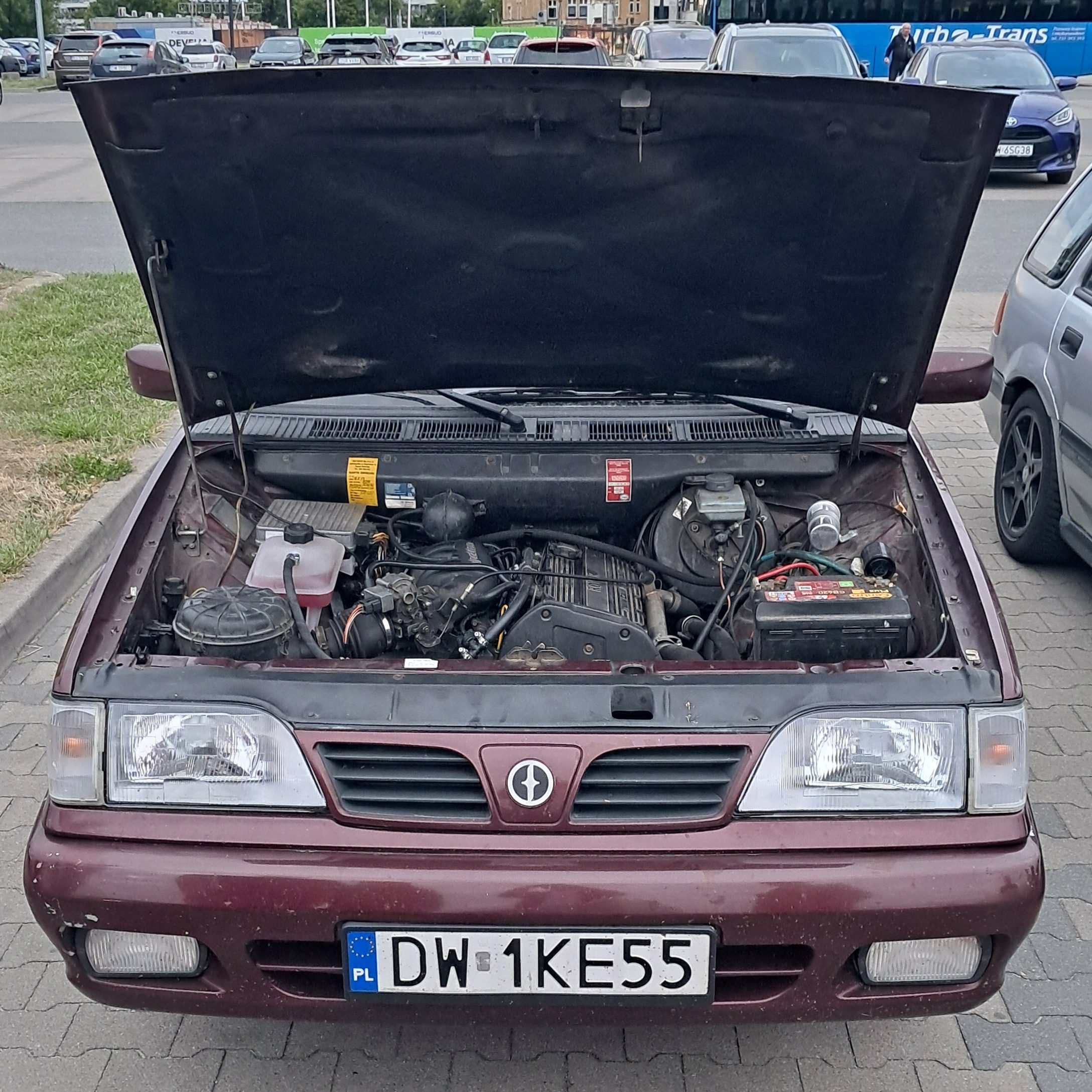
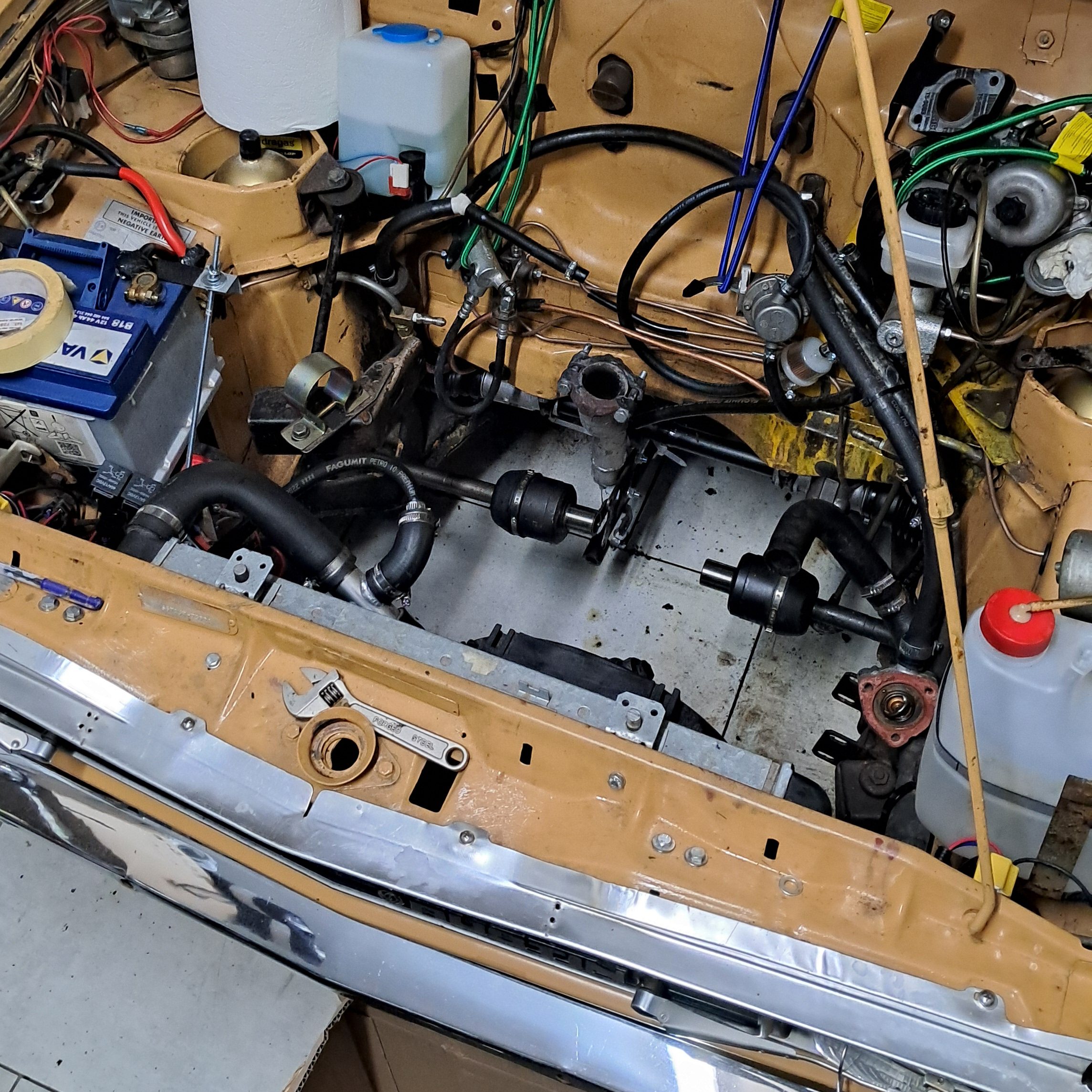
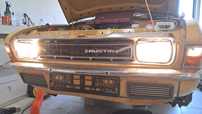
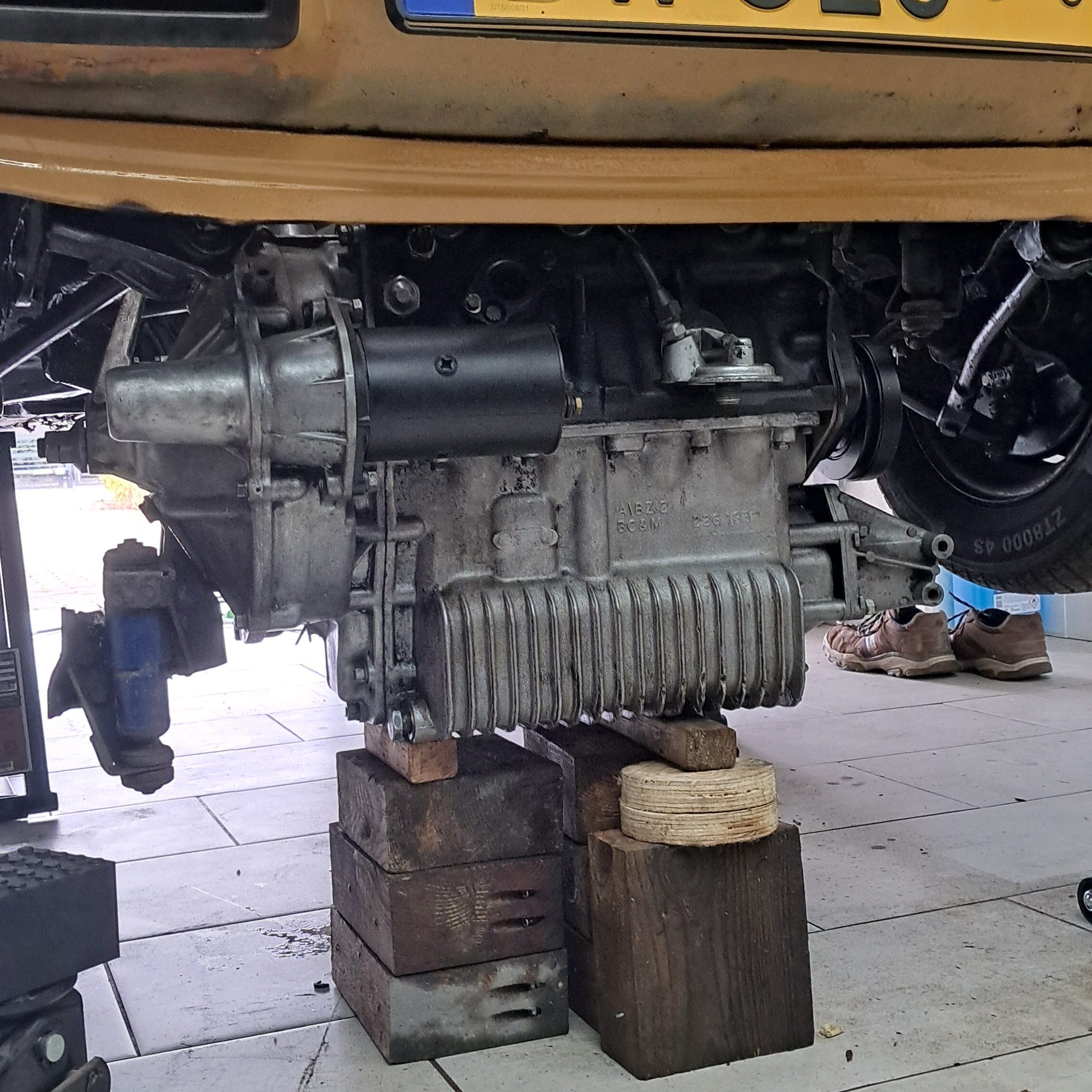
To make a bit of space, the final job on the engine for 2025 was to refit it in the bay with brand new bolts, since the original bolts looked like something from the Mary Rose.

2.3. CARB OVERHAUL

Another quick fix that turned into a battle lasting several days was to have a look at the carburettor to see what could be done about Agnetha’s fuel economy, or lack of it. I hadn’t calculated actual numbers for fuel consumption but it seemed “bus-like” and I wasn’t convinced that the thick carbon build-up on the spark plugs was due solely to oil fouling. Plus she was always very easy to start from cold which, for an A-series, all points to running heavily on the rich side. But it was during the early stages of the engine teardown, when I took the manifold off and half a cup of petrol fell out of the inlet and on to the floor, that I decided we had an over-fuelling problem and if I didn’t I solve that, it was going to make short work of my soon-to-be-rebuilt engine.

Once again vaguely recalling Agnetha’s recommissioning in 2023, I had rebuilt the carb but only got as far as replacing the throttle flap and the jet. For some reason the replacement fuel-bowl valve was still in a Mini Spares bag and I’d left the original, rather blunt needle in the carb. With the carb deconstructed on the bench I soon remembered why. The float didn’t want to be removed and, in those early days, I lacked the mechanical sympathy to know how hard I could hit anything seized in a shit quality, 50 year old aluminium casting, and what to do if something broke in the process – all I knew at that time was a new SU carb cost a lot more than the car was worth!

With a couple of years’ experience with calculated hammer usage built up since then, it was straightforward to remove the old float, replace the valve and swap the factory-fitted float for an ethanol-proof float that should easily outlive the rest of the car. The old valve was extremely worn and I’d put 10 quid on that alone being the root cause of the over-fuelling issue.

As for the needle, the absolutely useless aluminium retaining screw was seized. Despite a lot of soaking in WD40 and careful heating with a heat gun, I could not get it to shift and ended up shearing the head clean off. Lovely!

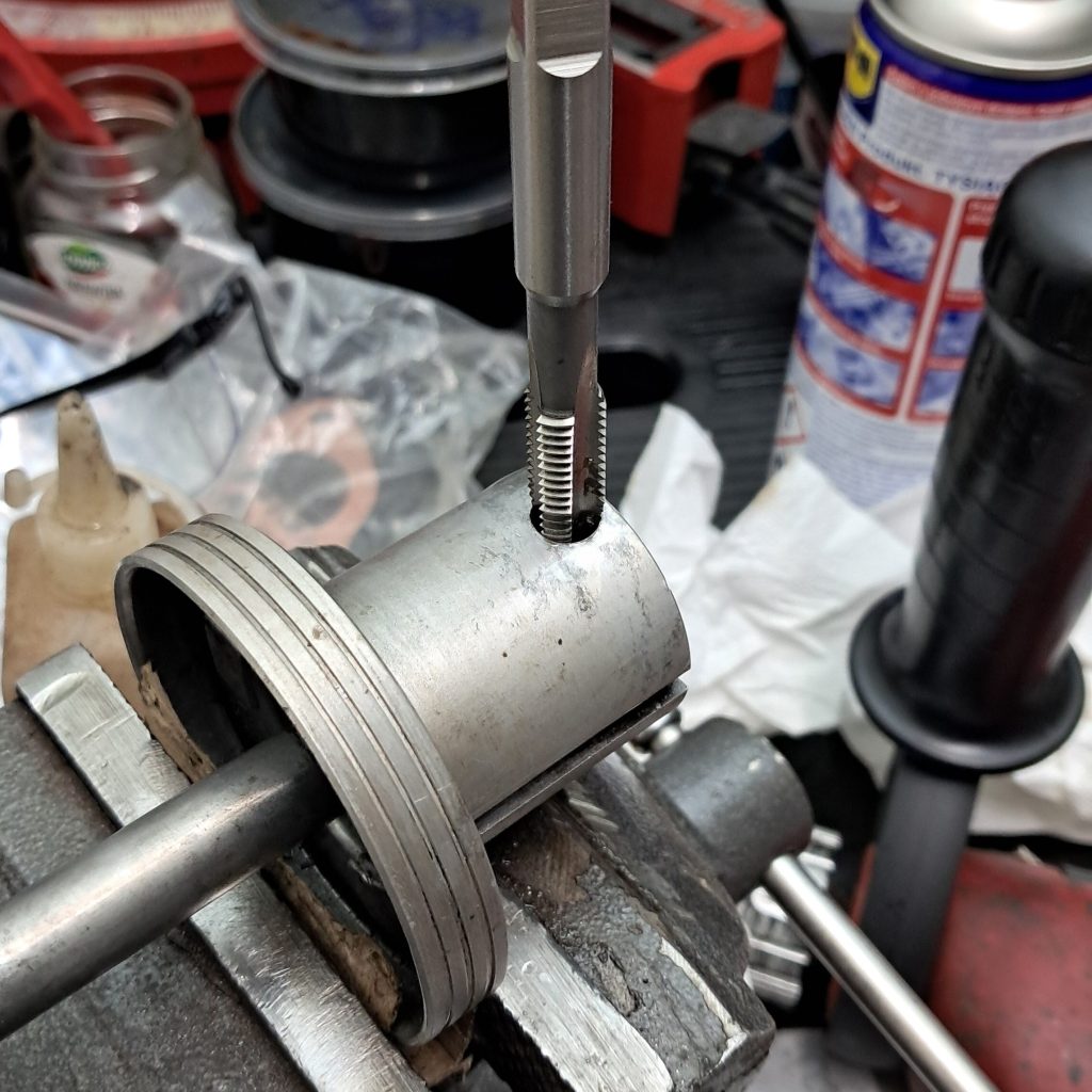
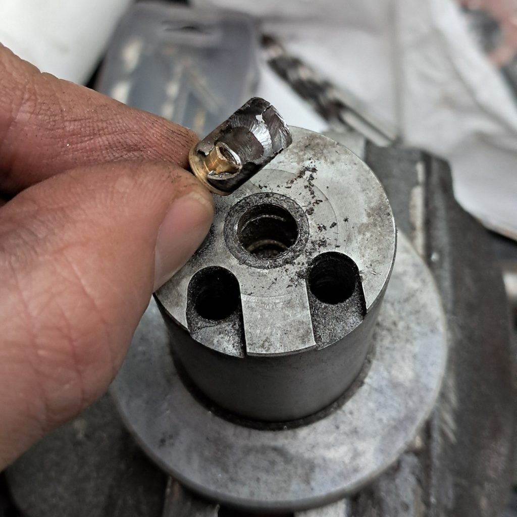
Eventually I had to drill out both the retaining screw and the needle. After some head-scratching and chin-stroking I replaced the utterly crap retaining screw with something more substantial: A helicoil and anodized steel grub screw that holds the needle perfectly in place and should come in very handy if I ever get into the mysterious world of needle tuning. And that’s it for the carb – but the only way to know if the fuelling problem is actually solved is to bung it on and fire it up.

3. outlook for next quarter

  • Cylinder head
  • Thoughts
  • Prayers
  • First start

Projekt Agnetha Quarterly Report 2025 Q3

Executive summary

Q3 represented a period of steady activity. Agnetha participated in multiple engagements, including the weekly Wrocław z Gratem meetup and a visit to the Wena Motor Museum, achieving her furthest recorded distance from base to date, not to mention a couple of shopping trips to Lidl and Biedronka. Key performance indicators demonstrated ongoing roadworthiness, with 290 km travelled and no breakdowns.

Engineering outcomes were, umm, mixed. Boroscope inspections confirmed the urgent need for a full engine rebuild due to cylinder wall damage and oil loss. This aligns with earlier assessments that outstanding technical debt, likely accumulating since the early 1980s, would need to be addressed sooner rather than later. It is also the most plausible single reason as to why she was taken off the road in 1989, not to return for 36 years.

Looking ahead, Q4 activities will be dominated by the engine rebuild, alongside preventative maintenance on the chassis and suspension. These interventions are expected to position Agnetha for a return to service in Spring 2026.

1. key performance indicators

Odometer(a)12345 km
Distance travelled this quarter(b)290 km
Furthest distance from home30 km
Breakdowns0

a)Odometer is undercounting due to faulty speedo cable, which makes it even more weird that when I checked the odometer *after* ripping out the engine it was stopped at 12345 I mean what the hell is that?

b)Estimated due to incorrect odometer readings.

2. MEETINGS, SHOWS AND OUTINGS

Wrocław z Gratem Meetup, Magnolia Park, Wrocław, 22nd August 2025

Agnetha had a surprise encounter in Magnolia Park with a fellow Longbridge stable-mate, a late model Rover 45 brought by visitors from the Netherlands.

Longbridge alumni

Another surprise was the sheer number of Rover K-series engines attending the meeting, thanks to the 45 showing up and the popularity of the engine with the FSO tuning scene. For a time, FSO had a 1.4 litre version of the K-series as an engine option for the Polonez Caro and Caro Plus. Although light and powerful, it was an expensive option, so the more meat-and-potatoes GM engines were the preferred choice.

I’m told these days there are more K-series-powered Polonezes than ever before, some with a lot more capacity than 1.4 litres, and no shortage of engineless Rover 25s, 45s and 75s piling up in scrapyards all around the country!

Muzeum Motoryzacji Wena w Oławie, 23rd August 2025

One of Planet Earth’s more startling examples of a hobby that got out of hand, the Wena Motor Museum is a must-see for any car enthusiast. And if you bring a classic car you’ll be invited to park in the middle by the friendly car park attendant.

Classics get to park in the middle.

This was Agnetha’s furthest travelled distance from home to date and unexpectedly her last trip of the season. On the way out the exhaust clamp came loose and, due to a persistent tailwind, it got a bit hairy with the fumes, even with both windows down. Heading into the wind on the return trip it was more survivable although at 90 kph I was once again attacked by petrified Swedish foliage blasting out from the vents. After this trip I noticed oil spatters around the end of the exhaust, and on checking the oil level she had lost about a cupful over just a short trip. Not a great sign.

Using a cheap boroscope I had a peak through the spark plug sockets into the cylinders. Each piston had a pool of oil and the damage to the cylinder walls was very obvious – game over!

Since her first start in May 2024 I knew she badly needed a full rebuild but at that time I had the rest of the car to fix as well, so my hope was to get her back on the road for at least one summer and have some fun. This much she gave, so I’ll call it a success, and now the debt must be paid.

3. ENGINEERING WORK

The focus of engineering activities this quarter were:

  • Removal and teardown of the engine
  • Diagnosis of the oil fouling situation
  • Assessment of necessary repairs and options for spare parts

3.1. COMPLETED

Engine Removal and Teardown

The engine was removed without a crane by lifting the body off the engine with the QuickJack, supporting the engine from underneath with wooden blocks and a floor jack. There was just enough clearance to pull the engine from under the car as long as the head was removed in situ beforehand, so it’s important to remember the head should also be fitted in situ after refitting the block in the engine bay – otherwise sad trombones all round when it won’t fit back under the car.

Contrary to the Haynes Book of Lies it was not necessary to disassemble the swivel hub assembly to remove the driveshafts from the diff. I wanted to avoid doing this because it also involves removing the callipers, draining the brake fluid, and so on. It turns out that disconnecting the swivel hub at the upper ball joint and at the trackrod end provides enough wiggle room to pull the driveshaft out of the diff. Besides which the brakes work fine – I’m supposed to be doing the engine not the effing brakes.

Oil Fouling Diagnosis

The root cause of the oil fouling was worn crankshaft thrust washers and worn main bearing shells allowing excessive lateral movement of the crankshaft. In short: Worn-out bottom end! This allowed the pistons to squirrel around inside the cylinders, scraping the cylinder walls with each stroke (as proven by horrendous witness marks on the pistons) resulting in excessive and uneven wear to the cylinder walls which, in turn, led to oil leaking around the piston rings and into the combustion zone. The widespread corrosion damage resulting from several decades of disuse was also not helping.

This degree of wear requires a lot of time and effort to accumulate. With over 123,000 km on the clock and a history of poor maintenance and neglect, we can assume that this is perhaps the main reason Agnetha was taken off the road 1989. There might have been other issues, but with oil fouling she would surely have failed her emissions test, an expensive engine rebuild was “off the table”, and so she was taken off the road and parked up…until 2025!

Repair Assessment

The block was sent to HT for assessment. Their recommendation was to bore the block out by two standard sizes to 1311cc. Oversized pistons have been purchased from MED Race Technologies along with a choice selection of fast road upgrades like-for-like(c) replacement parts.

The crankshaft is well within tolerance and shows no sign of uneven wear; it just needs a wee buff. The gearbox is in good condition, exhibiting no noticeable play or excessive wear on the gears. Apart from a good clean-out, no further work is needed.

Crankshaft only needs a polish and she’s ready to go.

Meanwhile at the cylinder head, the inlet valves seats need to be recut and the exhaust seats should be replaced completely with hardened seats better suited to unleaded petrol. All-new valves will be required by default, and the rocker assembly is certainly passed its best (if those rattling Pressed Steel assemblies ever had a ‘best’).

c) as in “this original part is like something retrieved from a sunken tractor, and it makes clear economic sense to swap it for this lightweight aerospace alloy component, which is more like what British Leyland should have put in there in the first place.”

3.2. PLANNED FOR Q4

The planned items are all focused on having the bottom-end “ready to go” by the end of the year:

  • Cylinders bored-out and honed, deck and crankshaft polished (outsourced to HT).
  • Speedo cable and gearbox attachment fixed.
  • Exhaust-to-differential mounting points repaired/rethreaded.
  • Bottom-end reassembled and reattached to transmission.
  • Timing mechanism reassembled and clutch/flywheel assembly installed.
  • Out of scope: Anything related to the cylinder head (planned for Q1).

While the iron donkey is out there are some 10-minute jobs(d) to do in-between the engine work:

  • A crack has formed on the passenger-side chassis leg and needs welding shut.
  • Both of the filler necks connecting to the fluid chambers of the front Hydragas displacers are too far forward, causing them to knock against the chassis legs. A bit of brute-force realignment should fix that.
  • The front suspension bump-stops disintegrated long ago. Replacements are in stock but installation requires depressurising the suspension and removing the displacers; this will happen anyway to repair the chassis legs and fix the knocking problem, so it’s a good opportunity to change the bump-stops as well.
  • A little preventative maintenance to remove surface corrosion, repaint and seal some surfaces that are looking a bit sad.

d)Minutes or hours? Are they interchangeable?

4. OUTLOOK FOR NEXT QUARTER

The Q4 priority is the full renovation and reassembly of the engine block.

Agnetha will be off the road for the rest of the quarter and likely for a good portion of 2026 Q1, but it’ll be winter, everyone will be spreading COVID around and the weather will be shit anyway. She’s on track to return to the road in time for Spring with a rebuilt, reliable, smooth-running and 100% stock engine.

Recommissioned and registered

Having passed her test yesterday, Agnetha had her temporary red plates exchanged for Historic Vehicle plates. Her new identity is DW 526. Recommissioning is officially complete – after 37 years or more, she is back on the road!

Now we enter the Rolling Restoration phase of the project. Still lots to do, but it will be a lot more fun to get her out and about! Who’s for a trip to Lidl?

Agnetha goes for a test – and passes!

The Big Push video ended on a bum note when a small error in the paperwork was discovered, putting everything on hold. While that was being sorted out I kept busy, replacing the sticking reverse light switch and doing a bit of cosmetic work (you know, try to make an effort kind of thing…). The corrected paperwork duly arrived and I was able to take out a 30 day temporary registration on Agnetha, effectively putting her back on the road for the first time since 1989.

Without being tested I could only legally drive her for the purposes of driving to a test centre. Since the test centre is a little bit out of town and involves a couple of 90kph stretches I might allegedly have bent the rules slightly to give her more of a low speed shake-down first. This involved driving to a nearby petrol station very early on Saturday morning to fill up – her first proper drink in 37 years or more. We then drove down the infamous Ulica Pawia (Peacock Street), a 19th century cobbled street that is more potholes than cobblestone. The idea was, if something was going to break, it would break there and then, and not too far from home. Impressively it all held together – just about. A few things which I won’t mention in public did manage to shake themselves loose but this was easily addressed at home with a spanner!

And so the time came. First thing this morning, against the rush-hour traffic Agnetha roared out of town towards the district test centre, the steering feeling tighter and the brakes nice and responsive. Along the two short 90kph sections I tickled her up to 70kph – she could have reached the speed limit easily but I decided not to push my luck. The test itself couldn’t have gone smoother – she behaved herself, didn’t dribble, crap herself or cause any kind of a scene.

And then we made our way home, this time with a test certificate in hand! But still cautiously keeping it to 70kph. The noise from the exhaust became incredible and I’m not sure if she managed to work the exhaust clamp loose – something to check before the next outing. But the final job to do before Agnetha formally enters the Rolling Restoration phase is to exchange the temporary plates for permanent yellow plates, then finally she can start to earn her keep on the supermarket run.

The Big Push

Got to admit I’m crap at keeping this blog up-to-date. Luckily everything is pretty much covered in this very long video in which I try to speed-run the final repairs before returning Agnetha to the road. Includes DIY custom exhaust fabrication!

It’s not supposed to be a steam engine

Towards the end of last year I noticed the problem of coolant leaking from around the engine head studs was getting worse. My solution of “ignoring it” wasn’t having much of an effect, surprisingly. After running her up to temperature one day the coolant was freely bubbling out of all the studs and even from the head gasket itself. This clearly wasn’t going to fix itself. It was time to take the head off!

This was pretty straightforward as I’d only replaced the head in May 2023 after installing new valves, so it came apart very easily and the cause of the problem was pretty clear: I’d made a beginner’s mistake and forgotten to tighten up the head studs! Most of them were barely finger tight. Obviously the cylinder head didn’t have a reliable seal with the head gasket but – as it turns out – the holes that the studs screw into lead directly into the water jacket and have to be tight to stop the coolant escaping.

The cylinder head surface itself didn’t have any obvious defects, warpage or signs of head gasket failure so I didn’t bother getting it machined. The pistons and valves, however, were caked-up with black, oily deposits. It wouldn’t surprise me at all that the piston rings need replacing but I’ll save this for when it gets a complete rebuild, after Agnetha has been tested and registered.

Having thoroughly cleaned all the studs and surfaces I made sure the studs were tightly screwed into the block this time using the two-bolt method and a healthy glob of Loctite on each thread. With a new gasket and the nuts tightened, she started up first time with no issues and got to temperature without a drop of coolant spilled. After cooling down, I retorqued the nuts and still no puddle of coolant on the floor. Just the usual puddles of steering rack oil and brake fluid, but we’ll cross those legs when we get to them.

Wrapping up 2024 – so close!

It’s been a big year for Agnetha and, if all goes to plan, she’ll return to the road early in the New Year. Since my previous post I’ve been putting the interior back together and fiddling about with the cooling system as shown in these videos:

Most recently Agnetha had her first tyre change this century and, judging by the 1977 date codes of the old tyres, possibly her 2nd tyre change ever. And she had one final trick up her sleeve: Allegro wheel rims are normally 145R13 or 155R13 but Agnetha’s are 175R13. It turns out there are a handful of surviving LHD Allegros with this slightly chunkier size so presumably it was some kind of regional requirement. Works fine for me though, because there is a plenty of choice for rubber in this size. In the end I opted for Zeetex all-seasons with a 50% discount and free overnight delivery – very rare to get such deals on spares for an Allegro!

Putting the new tyres on became urgent as the brakes now work very well and after a few brake checks I noticed the old tyres were starting to tear!

Finally, it was time to check a couple more details off the list. The battery clamp was one of the few components that was entirely missing from Agnetha when I bought her in 2022. After some intensive chin-scratching in the aisles of Castorama I was able to cobble-up a convincing clamp from some threaded rod, a pair of wingnuts and a 90 degree steel profile. To prevent any unwelcome excitement with shorting the battery terminals I made sure to insulate the profile with duct-tape (black, for increased resistance…) Last but not least I figured out how to connect the breather pipes, brake servo, manifold and carb correctly, in the absence of BL’s Heath-Robinson emission control system (which was a pile of crap, apparently)

With Agnetha’s breathing sorted out I tried a little carb tweaking to bring the idle and raucous cold-start under control. Doing this I found a massive vacuum leak coming from the seal between the master cylinder and the servo. With that corrected it was quite easy to set the idle and choke settings for a smooth and undramatic start, hot or cold.

All that remains now is to fit a new exhaust, tend to a little welding near the rear swing-arm mounts and fit new bushings/seals to the steering rack; the first job of 2025 will be to find a workshop to take of all that on and get it tested and registered. Then at last we’ll be ready for the inaugral supermarket run!

Effective braking

It took a few goes (and some physical effort) to thoroughly bleed Agnetha’s hydraulic brake lines, but we finally got there and all of sudden she stops as well as drives. She’s very close to getting back on the road now: Exhaust, a bit of welding and some fettling with the steering rack – will she be registered in time for her 49th birthday in May?

Hydragas and The Impossible Repair

Having achieved some form of brake pedal it was at last time to tackle the Bogeyman of Agnetha’s recommissioning: The suspension.

what is hydragas?

Being an Austin Allegro, Agnetha’s suspension is anything but conventional. The Allegro is one of a handful of vehicles developed to use the Hydragas suspension system developed by Alex Moulton of folding bike fame. I won’t go into detail about how it works because others that know a lot more have already done that. But here’s my over-simplified airline magazine explanation:

For each wheel on the car you’ve got a displacer pushing down on it. A displacer is basically a Star Wars prop that contains a fluid chamber and a sphere. The sphere contains a high pressure inert gas and is seperated from the fluid chamber by a rubber diaphragm. The displacer works like a piston that pumps a water-based fluid in and out of the fluid chamber when the wheel moves up and down. Displacers work in pairs: One pair for the left-hand side of the car, the other pair for the right-hand side. In each pair the fluid chambers of the displacers are connected by a hydraulic line running the length of the car. This means when the front wheel moves up, fluid is moved out of the front displacer and into the rear displacer, pushing the rear wheel down and resulting in a self-levelling effect.

The layout of displacers and fluid lines (adapted from Haynes)

The fluid is pumped up to high pressure through Schrader valves in the filler necks, and that sets the car’s ride height. The spheres and the upper diaphragm are there to absorb shock loads. Unlike Citroën’s Hydropneumatic system, Hydragas is passive in that it has no pump to maintain pressure of the fluid or gas components, and it is completely isolated, having nothing to do with brakes are any other ancillaries. So mechanically it’s about as simple as it can possibly be. And that’s Hydragas in a nutshell. It’s a highly effective, cheap and quite simple solution let down by only two minor problems: 1) It’s technologically extinct, and 2) it has a 100% failure rate. Oopsie. Let’s have a look at these in more detail.

technologically extinct

As mentioned, only a handful of cars used Hydragas and all of them were from the strange world of British Leyland in its various historical guises, specifically: Allegro, Maxi (later models), Princess, Ambassador, Metro and MG F. The most recently manufactured of these cars, the MG F, went out of production in 2002 – over 22 years ago at the time of writing. This means NOS parts, particularly the displacers, are vanishingly rare and, even if you found one, will likely need some work to recommission them as we’ll see later. There are one or two companies that sell reconditioned sets of displacers, and one is particularly reknowned, but globally this is pretty much the only support you’re going to get unless you’re lucky enough to know some wise wizard that still practices the dark arts, hasn’t scrapped their “dalek“, and never really planned on retiring anyway. Outside the UK you’re going to be hard-pressed to find someone that ticks all of those particular boxes!

100% failure rate

This “statistic” is bandied around a lot and although it’s not really a statistic I think there’s a lot of truth in it. Hydragas relies on components being under constant high pressure and any system under pressure will inevitably leak. As long as the pressures of both the inert gas in the spheres and the suspension fluid are optimum, there’s nothing much to worry about. But the gas continually leaks from the spheres, and this is completely unavoidable. So the displacers were designed to leak at a low enough rate that they would be serviceable for at least 15 years (the intended life expectancy of the Allegro – compare that with any modern car!). Once below a critical pressure, however, Hydragas enters the infamous death spiral.

The Hydragas death spiral.

As death spirals go, Hydragas has a particularly interesting one, and once started it cannot be stopped without major intervention. With the shock-absorbing effectiveness of the spheres reduced, the shocks begin to affect the hydraulic unions causing a slight amount of suspension fluid leakage. This reduces the fluid pressure, reducing the ride height, and subsequently increasing the ride hardness, further reducing the shock-absorbing effectiveness of the spheres and exacerbates the fluid leakage. And so it goes on until the suspension has no softness at all and the car is sitting on the bump-stops. As we get closer to the middle of the spiral, the risk of suspension failure increases dramatically. Failure can be in the form of fluid/gas diaphragm rupture in one or more displacers, or even as structural damage to the suspension arms and strut towers.

It might be tempting to refill the fluid lines on seeing the car’s ride height reduce. This will return the car to its intended ride height but will not make the ride softer and only tightens the spiral. The increased pressure in the fluid lines simply worsens the leakage and puts additional strain on the fluid/gas diaphragm.

So what do we need to do? Back in “them days” you would simply order a brand new set of displacers with optimum gas pressure and have them fitted as if you were replacing worn-out coils or broken springs. As we’ve already discussed, this is sadly no longer an option.

sphere re-gassing

The sensible option at this stage is to order a set of reconditioned displacers from The Kennedys. These are used displacers that have had Schrader valves installed in the spheres so that they can be re-gassed whenever needed. I eventually got around to ordering a set, but not before spending a huge amount of time getting my hands dirty trying to re-gas the displacers myself! I don’t think I’d try this on a car that was otherwise in good working order, but with Agnetha there was nothing much to lose.

DISCLAIMER: These are not instructions! It’s an account of what I did, for better or worse. You may cause irreparable damage to the car or its components – ask me how I know.

To re-gas the displacers I followed the method documented here, more-or-less. It basically involves drilling a hole in the top of the sphere (very carefully!) and attaching a heavy-duty Schrader valve (the type used on truck and bus wheels). Using the valve you can re-pressurise the sphere with nitrogen to the prescribed 15 bar. Compressed air is basically nitrogen, right? There is, naturally, a catch. If a displacer has spent any time on the death spiral – or if the suspension fluid was “accidentally” topped up with brake fluid or LHM (the Kiss of Death) – there is a chance it will have a ruptured fluid/gas diaphragm. Common knowledge amongst Hydragasologists says that a ruptured fluid/gas diaphragm is an Impossible Repair and the displacer cannot be re-gassed or re-used in any way; it’s scrap. As you’ll see I’ve found no evidence to contradict this.

On drilling the hole for the Schrader, sure enough one of the front displacer spheres was full of rusty water. Gas/fluid diaphragm failure! The Impossible Repair! Doom! Failure! But what have I got to lose by trying something impossible? I decided to saw the sphere carefully in half manually using a hacksaw so as not to blast whatever was inside to smithereens. After cleaning the inside I noticed the gas/fluid diaphragm indeed had two small holes and was perished around the circumference. It does seem impossible to replace the entire diaphragm but what about patching it?

At this stage anything was worth a try. Using a tractor inner tube repair kit I patched the two holes and sealed the circumference with a generous amount of Soudal Fix All, a very strong elastic glue.

Now to weld the sphere back together. Should be fun welding so close to all that glue and rubber! First I made a collar from a sheet of car body steel to fit inside the sphere that would sit about 1 – 2mm proud of the cut. This was to prevent sparks from the welder entering the sphere and burning the diaphragm. It might have also helped keep the Fix All in place when the water circuit was pressurised – unfortunately I didn’t get that far! To keep the heat under control I then filled it with water.

With the collar in place I began welding the top half of the sphere to the rest of the unit, very slowly and carefully. The welds were ugly and porous due to steam rushing out alarmingly from under the collar, but the water did its job and kept the rubber and glue from burning. After grinding the welds back it was not as bad a job as I thought, the welds showing good penetration all round but the seam had numerous holes where the steam had escaped. I was able to patch the holes by welding over the entire seam using a slightly lower feed-rate, again slowly and carefully. These welds were only ground back a little bit to reduce the height so that the unit could fit inside the suspension tower – given what’s a stake I prefer integrity over aesthetics!

After that we were back on the map: Install the Schrader, make sure it takes a few bar of compressed air, then a good clean up and paint. Unfortunately, after pumping up to 10 bar and leaving overnight to test for leaks, I measured only 3 bar the following morning. A leaking Schrader could be easily fixed, but if the leak is through the diaphragm it would be time to call it quits. To test this I pumped it back up to 10 bar and put the thumb of a rubber glove over the fluid port of the displacer. If the air leaks through the diaphragm then the thumb will inflate. Sure enough, the next day we were back to a couple of bar and the thumb was certainly inflated – time to throw in the towel.

This is when I placed an order with The Kennedys and a few days later a set of reconditioned displacers arrived, fully tested with a 1 year guarantee; the installation of which was only complicated by my poor plumbing skills. I recorded it all in this video:

I’m pleased to report that Agnetha is now as bouncy as she can be. Two years into the restoration, mechanically and structurally she is almost ready for the road again for the first time in 35 years. She still needs a new exhaust and there is a list of minor snags to fix first, but nothing to cause any major worries. In fact, it’s nearly time to get some workshop quotes to get her over the line and tested at last.

Last but not least, I ordered some reproduction engine bay stickers from Miniphernalia and put them on the strut towers. It’s got to look right!

Another Bright Idea

Once again Agnetha is up in the air with wheels off. This time she’s being prepped for receiving a reconditioned set of Hydragas displacers from The Kennedys and having her suspension pumped up for the first time in many years. This will be a huge milestone as it’s almost the last major repair to do before testing! But let’s not get ahead of ourselves. While I wait for the displacers to make their way to the Slavic Paradise I wanted to try a small upgrade that could improve Agnetha’s safety in modern traffic.

It’s an in-joke in the classic car world to talk about having headlights like a glow-worm in a jar. Headlights on older cars tend to be dim due to a) the ridiculous physical length of the headlight circuits, and b) surface oxidation of the copper strands in the wiring loom and switch-gear. Even for a small car like the Allegro the headlight circuit is very long, starting at the battery, going through the firewall, into the centre console where the headlight/sidelight switch is located, then up into the steering column and around the main beam / flash stalk, back through the firewall, along the wing into the right-hand headlight and then under the radiator into the left-hand headlight. It’s insane, really. Even from the factory the total resistance would have been considerable, and after several decades it will be quite a lot more.

Indeed I had noticed the wiring and switches would heat up quite quickly with the headlights on. So the net result is dim headlights and the constant threat of an electrical fire or a sudden loss of headlights – not something I want to be thinking about on a dark night at 90 kph in the middle of the Polish countryside. Luckily there is a solution that is cheap and fairly simple to install: A classic car wiring loom. These normally come in the form of a ready-assembled kit that can be installed “over” the original wiring loom without interfering with it. While looking online I saw some classic car specialists had these for sale at very silly prices. But it’s just not worth paying a lot for these things – they’re all made of the same components and it does not need to be anything special. I bought the cheapest piece of crap I could find – for about £11!

For a little over a tenner you too can have headlights that actually do something.

The kit works by powering the headlights through a pair of relays (one relay for the headlight, the other for main beam). The current only travels a short distance over brand new wires, reducing the resistance by reducing the length of the circuit and also avoiding the increased resistivity of the original, now rather oxidised wiring. The original wiring is kept in place, however, because it’s used to control the relays by supplying voltage to energise the relay coils. Since this requires very little current, there are no longer any issues with resistance heating. Installation simply involves connecting the “big red wire” of the kit to the positive terminal of the battery, connecting the output plugs of the kit into the headlights, and connecting one of the original headlight plugs (the one nearest the battery) into the input socket of the kit; the remaining plug from the original wiring is then redundant and can be taped-up. It’s then just a case of testing and tidying things up.

And this is when I found the one and only snag. While the headlights and main beam worked as expected, the main beam flash wasn’t working when the headlights were on. I could hear the relay clicking but there was no change in the light pattern. After some poking around I realised this was because the relays were wired in such a way that the main beam could not be switched on if the headlight relay was in the “on” position. This was solved by bridging the wires connected to terminal 30 on both relays. With this in place the main beam flash was working, as was everything else.

The relays, stuck to the battery tray with extra-strong double-sided tape. The wires connecting to terminal 30 had to be bridged for the main beam flash to work.

I haven’t done any scientific tests to prove how big an improvement this is. I’ve just looked at the headlights and said “wow they’re brighter” and felt the wiring to be sure they no longer heat up. For 11 quid I’d call that a result. Much brighter headlights and no more hot plastic smells!